Air path arrangement for pneumatic nail gun

a pneumatic nail gun and air path technology, applied in the direction of nailing tools, manufacturing tools, stapling tools, etc., can solve the problems of high manufacturing cost, inability to improve the competitive price of nail guns in the market, and time-consuming task of assembling large number of parts

Inactive Publication Date: 2007-06-05
SAMSON POWER TOOL
View PDF12 Cites 42 Cited by
  • Summary
  • Abstract
  • Description
  • Claims
  • Application Information

AI Technical Summary

Benefits of technology

[0005]The present invention will become more obvious from the following description when taken in connection with the accompanying drawings which show, for purposes of illustration only, a preferred embodiment in accordance with the present invention.

Problems solved by technology

However, the function requires a special path arrangement in the nail gun and a large number of parts are involved to achieve the purpose.
The parts are installed in the limited space in the nail gun and require high standard of precision of machining so that the manufacturing cost is so high that the nail gun do not have better competitive price in the market.
Besides, to assemble the large number of parts is a time-consuming task which includes the labor cost.

Method used


Image

  • Air path arrangement for pneumatic nail gun
  • Air path arrangement for pneumatic nail gun
  • Air path arrangement for pneumatic nail gun

Examples


Embodiment Construction

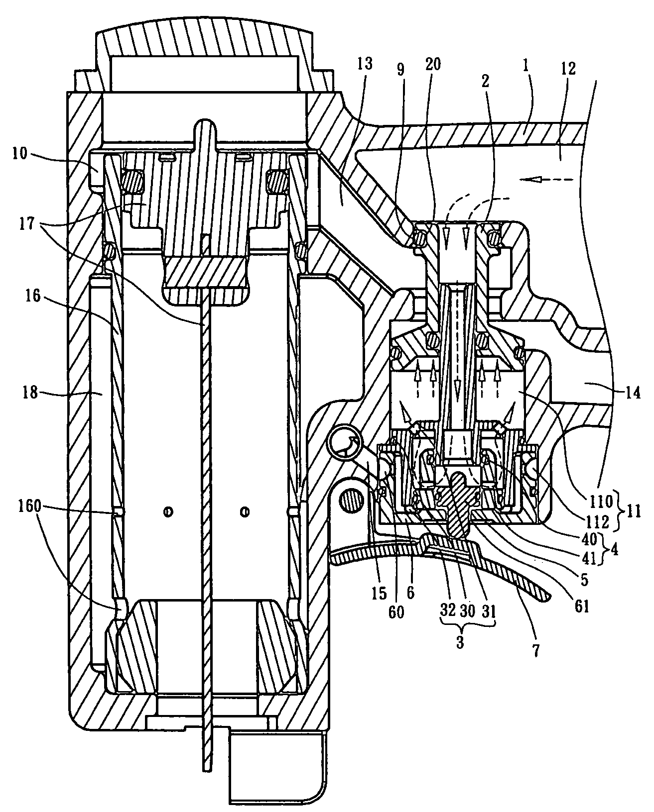
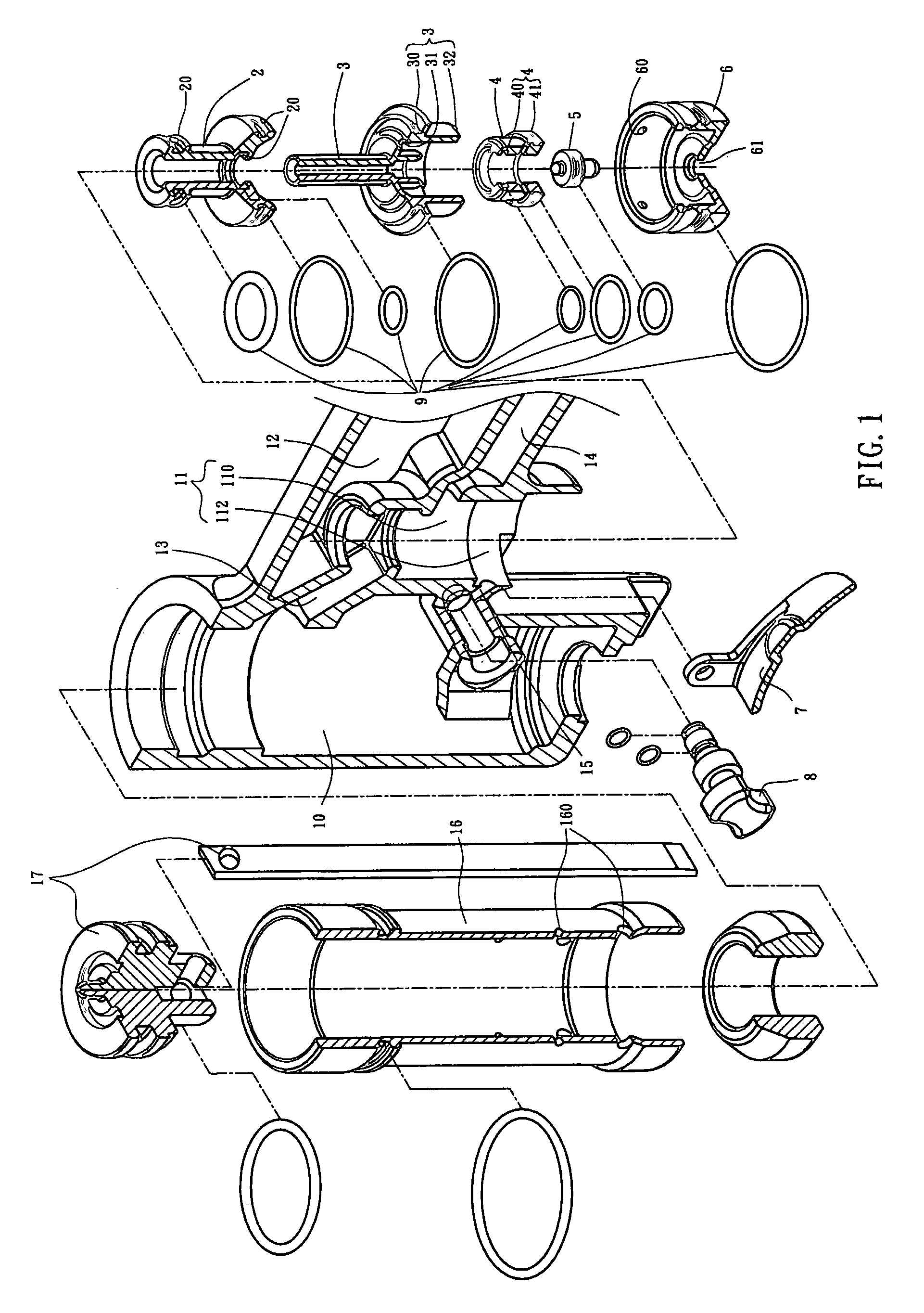
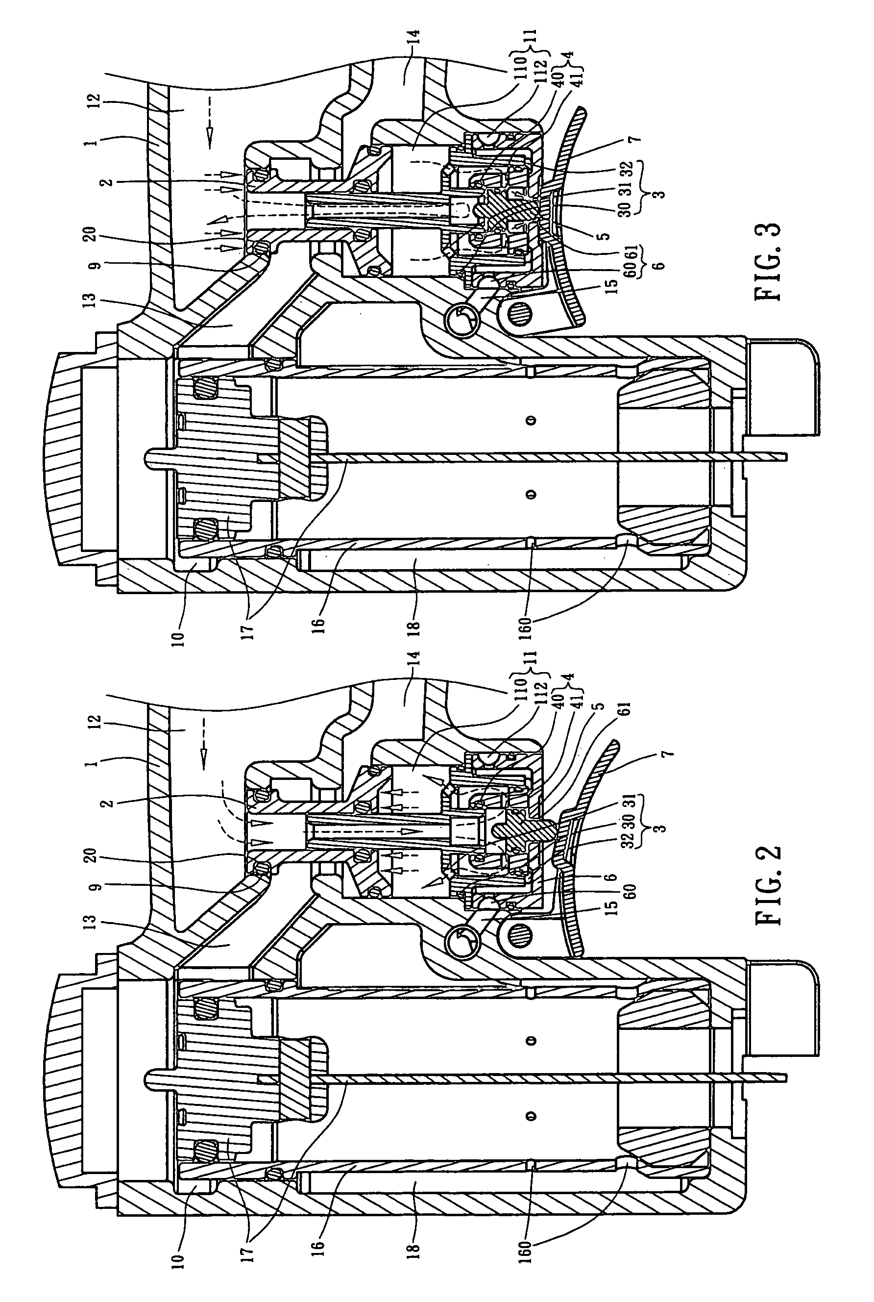
[0013]Referring to FIGS. 1 to 6, the air path arrangement for a pneumatic nail gun of the present invention comprises a body 1 which includes a barrel and a handle which is connected to the barrel. The barrel has an interior 10 defined therein and a cylinder 16 is received in the interior 10. A piston unit 17 is received in the cylinder 16, and a space 18 is defined between the cylinder 16 and an inner periphery of the barrel of the body 1. A chamber 11 is defined in the handle connected to the barrel and includes a first partition 110 and a second partition 112. A connection path 13 communicates between the interior 10 and the first partition 110 of the chamber 11. A side path 15 communicates between the space 18 and the second partition 112 of the chamber 11. The first partition 110 communicates with an inlet 12 and an outlet 14 in the handle.

[0014]A movable member 2, a guide member 3, a valve 4, an axle 5 and a base 6 are received in the chamber 11. The movable member 2 is a holl...


PUM

PropertyMeasurementUnit
movementaaaaaaaaaa
areaaaaaaaaaaa
speedaaaaaaaaaa

Abstract

An air path arrangement for a pneumatic nail gun includes cylinder received in a barrel and a handle is connected to the barrel. A space is defined between the cylinder and an inner periphery of the barrel. A connection path communicates between the interior and a first partition of the chamber. A side path communicates between a space between the cylinder and an inner periphery of the barrel, and a second partition of the chamber. The first partition communicates with an inlet and an outlet in the handle. A movable member, a guide member, a valve, an axle and a base are received in the chamber. The guide member is located between the first and second partitions. The guide member has apertures which communicates with the first and second partitions so that the movable member and the valve are movably received in the first partition and the second partition.

Description

FIELD OF THE INVENTION[0001]The present invention relates to an air path arrangement for pneumatic nail gun and includes less number of parts.BACKGROUND OF THE INVENTION[0002]A conventional pneumatic nail gun is able to continuous shoot with one pull of the trigger. However, the function requires a special path arrangement in the nail gun and a large number of parts are involved to achieve the purpose. The parts are installed in the limited space in the nail gun and require high standard of precision of machining so that the manufacturing cost is so high that the nail gun do not have better competitive price in the market. Besides, to assemble the large number of parts is a time-consuming task which includes the labor cost.[0003]The present invention intends to provide an air path arrangement for a pneumatic nail gun and the arrangement does not need a large number of parts and the parts are easily to be assembled.SUMMARY OF THE INVENTION[0004]The present invention relates to an air...

Claims


Application Information

Patent Timeline
Patent Type & Authority Patents(United States)
IPC IPC(8): B25C5/06
CPCB25C1/043
Inventor LEE, YI KUAN
Owner SAMSON POWER TOOL
Why Eureka
Try Eureka