Nail gun switch mechanism

a switch mechanism and nail gun technology, applied in the direction of nailing tools, manufacturing tools, stapling tools, etc., can solve the problems of a complicated structure of the rotating rod, and achieve the effect of simplifying the structure of the nail gun switching mechanism

Inactive Publication Date: 2010-10-12
ROBERT BOSCH TOOL +1
View PDF21 Cites 36 Cited by
  • Summary
  • Abstract
  • Description
  • Claims
  • Application Information

AI Technical Summary

Benefits of technology

[0007]To overcome the above-mentioned problems, an objective of the present invention is to provide a nail gun switching mechanism in which a single touching surface can be swung between two positions to respectively touch a trigger lever so as to simplify the structure of the nail gun switching mechanism.
[0009]In this embodiment, the structure of the swing arm is simpler compared with the rotation rod in the related art while maintaining the capability of switching between different actuation modes. Hence the present invention is suitable for rapid mass production.

Problems solved by technology

However by having the two shoulders respectively touch the trigger lever during actuation mode switching, the rotating rod generally has a complicated structure, which needs to be improved.

Method used


Image

  • Nail gun switch mechanism
  • Nail gun switch mechanism
  • Nail gun switch mechanism

Examples


Embodiment Construction

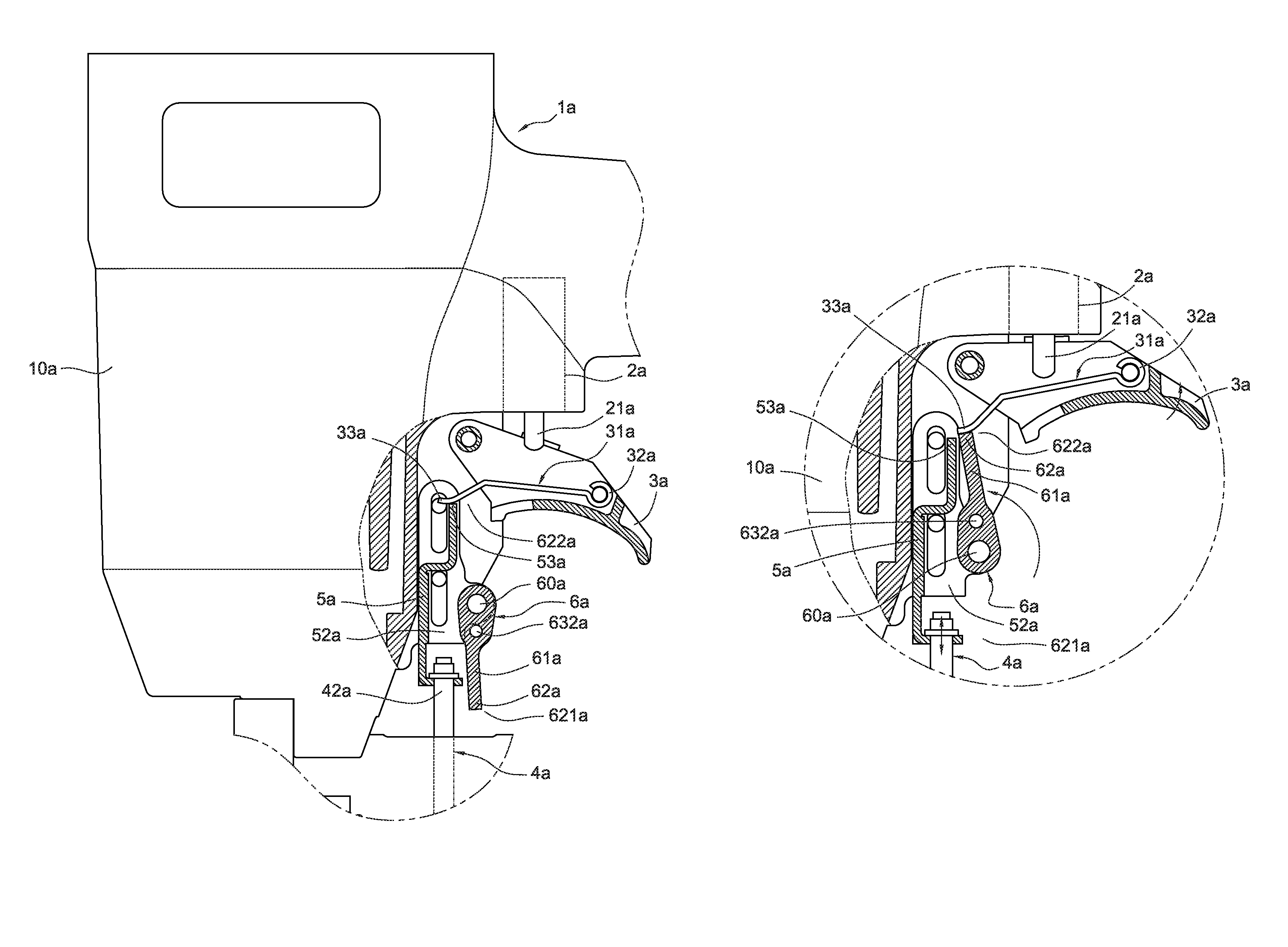
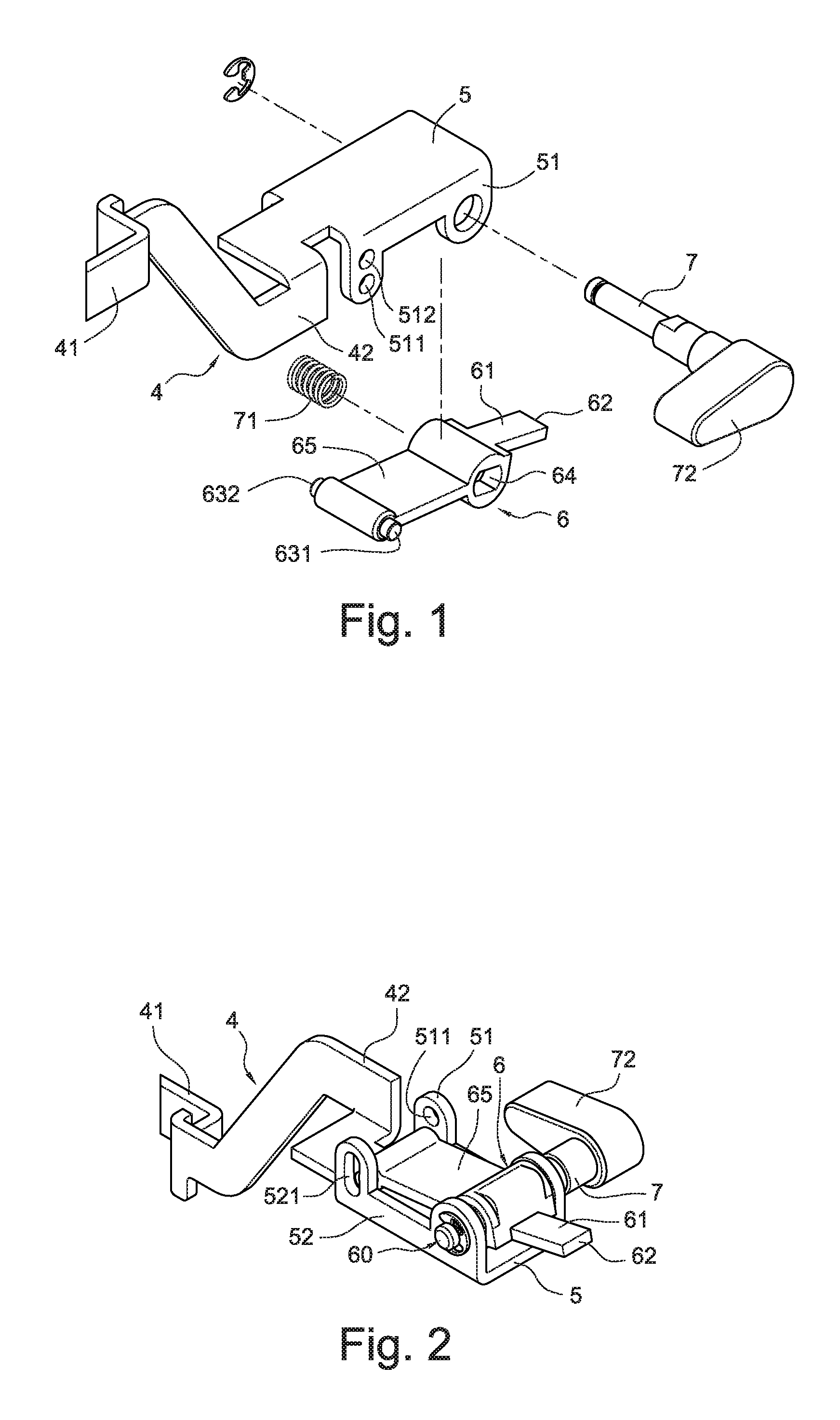
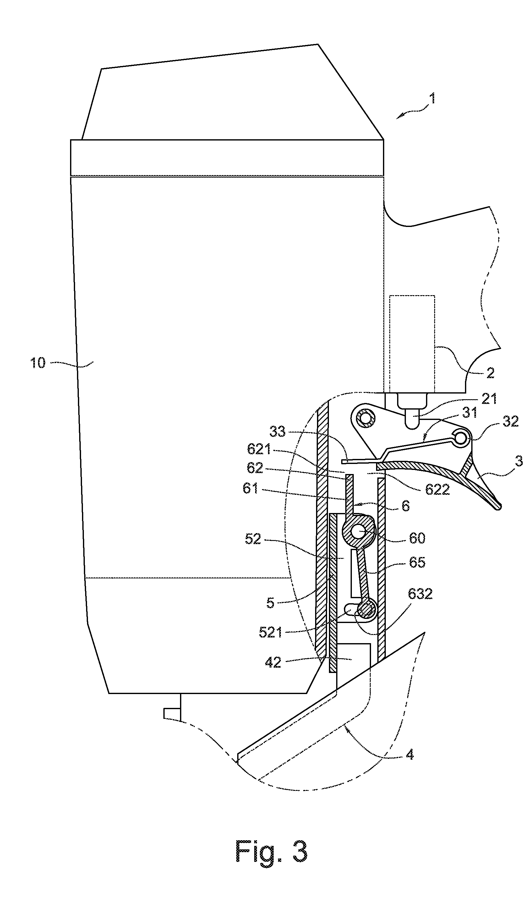
[0040]FIGS. 1 to 3 disclose a nail gun switch mechanism according to a first embodiment of the present invention. A nail gun 1 has a gun body 10 and a trigger 3. A trigger valve 2 is disposed in the gun body 10. A trigger lever 31 is pivotably disposed in the trigger 3 configured for driving the trigger valve 2 to open. A safety slidable bar 4 is slidably disposed on the gun body 10. A bottom part 41 of the safety slidable bar 4 extends to the outside of a hitting mouth at a bottom of the gun body 10. A top part 42 of the safety slidable bar 4 extends near to an end of the trigger 3.

[0041]The trigger lever 31 has a pivot base 32 (as shown in FIG. 3) at one end pivotally disposed on the sidewalls of the trigger 3, and a tongue part 33 at another end. When the tongue part 33 and the pivot base 32 of the trigger lever 4 are pushed or brought to move upwardly (as shown in FIG. 8), an intermediate portion of the trigger lever 31 can push the trigger valve bar 21 so as to drive the trigge...


PUM

PropertyMeasurementUnit
elasticaaaaaaaaaa
radiusaaaaaaaaaa
elastic forceaaaaaaaaaa

Abstract

A nail gun switch mechanism includes a gun body and a trigger. A safety slidable bar has a bottom part which extends outside of a hitting mouth at a bottom of the gun body. The trigger has a trigger lever being pivotably disposed therein. A top part of the safety slidable bar extends near to an end of the trigger and a swing arm is pivotably disposed on the top part of the safety slidable bar. The swing arm includes an arm part extending from a pivotal center of the swing arm and a push part extending from the arm part toward outside. The push part is configured to be switched to a first or a second swing position and thus driven by the safety slidable bar to touch the trigger lever so as to operate the nail gun in a sequential or a contact actuation mode.

Description

BACKGROUND[0001]The present invention relates to a nail gun switch mechanism, and particularly to a nail gun switch mechanism for switching the nail gun operation in a sequential actuation mode and a contact actuation mode.[0002]In pneumatic nail guns, a hitting bar is driven by compressed air momentarily to push a nail into a workpiece. The hitting bar is controlled cooperatively by a trigger and a safety slidable bar on the nail gun body or a hitting base connected with the safety slidable bar.[0003]Actuating nails for a pneumatic nail gun generally can be divided into two kinds, one is the sequential actuation mode (or the restrictive mode) and the other is the contact actuation mode.[0004]The sequential actuation mode means the operator firstly should set a safety slidable bar or a hitting base on the safety slidable bar contacting on a workpiece to push an upward movement of a trigger lever, and then press a trigger to bring the trigger lever to actuate a trigger valve. In this...

Claims


Application Information

Patent Timeline
Patent Type & Authority Patents(United States)
IPC IPC(8): B25C1/04
CPCB25C1/008
Inventor WU, YI-TSUNGCOLE, JR., STEVEN WYNNE
Owner ROBERT BOSCH TOOL
Why Eureka
Try Eureka