Clutch Mechanism for Electrical Nail Gun

a clutch mechanism and nail gun technology, applied in the direction of nailing tools, stapling tools, manufacturing tools, etc., can solve the problems of affecting safety and stability, complicated structure of the clutch assembly, and improving the service life of the nail gun, so as to reduce the lifetime of the nail gun

Active Publication Date: 2009-02-05
ROBERT BOSCH TOOL +1
View PDF19 Cites 34 Cited by
  • Summary
  • Abstract
  • Description
  • Claims
  • Application Information

AI Technical Summary

Benefits of technology

[0007]What is needed, therefore, is to provide a rotational kinetic energy clutch mechanism for an electrical nail gun, which by not using a wire to transmit the hitting force overcomes the problems of reduced lifetime of the nail gun and generating a component force misaligned with a desired nail hitting direction after long-term use.
[0014]Based on the above-mentioned, the clutch mechanism in accordance with the present invention improves service life of the electrical nail gun because the flywheel is rotated to directly mesh with the sliding base. Furthermore, the clutch mechanism is unlikely to generate a component force misaligned with a desired nail hitting direction during long-term use of the electrical nail gun, thereby improving the durability of the clutch mechanism for the electrical nail gun in long-termed use of the electrical nail gun.

Problems solved by technology

However, the structure of the clutch assembly is complicated due to too many components, and it is a disadvantage to improve service life of the nail gun because the driving base is pulled by a rope to move downwardly to hit nails.
However, during a long-term use, an abrasion may be produced by friction between the roller, the driving base, and the flywheel to thereby broaden mesh clearance.
When the driving base of the hitting nail bar is pushed by the roller towards the flywheel to mesh with the flywheel, a component acting force is produced not along a direction of impacting the nail due to clearance, thereby affecting safety and stability as the driving base is driving the hitting nail bar to impact the nail.

Method used


Image

  • Clutch Mechanism for Electrical Nail Gun
  • Clutch Mechanism for Electrical Nail Gun
  • Clutch Mechanism for Electrical Nail Gun

Examples


Embodiment Construction

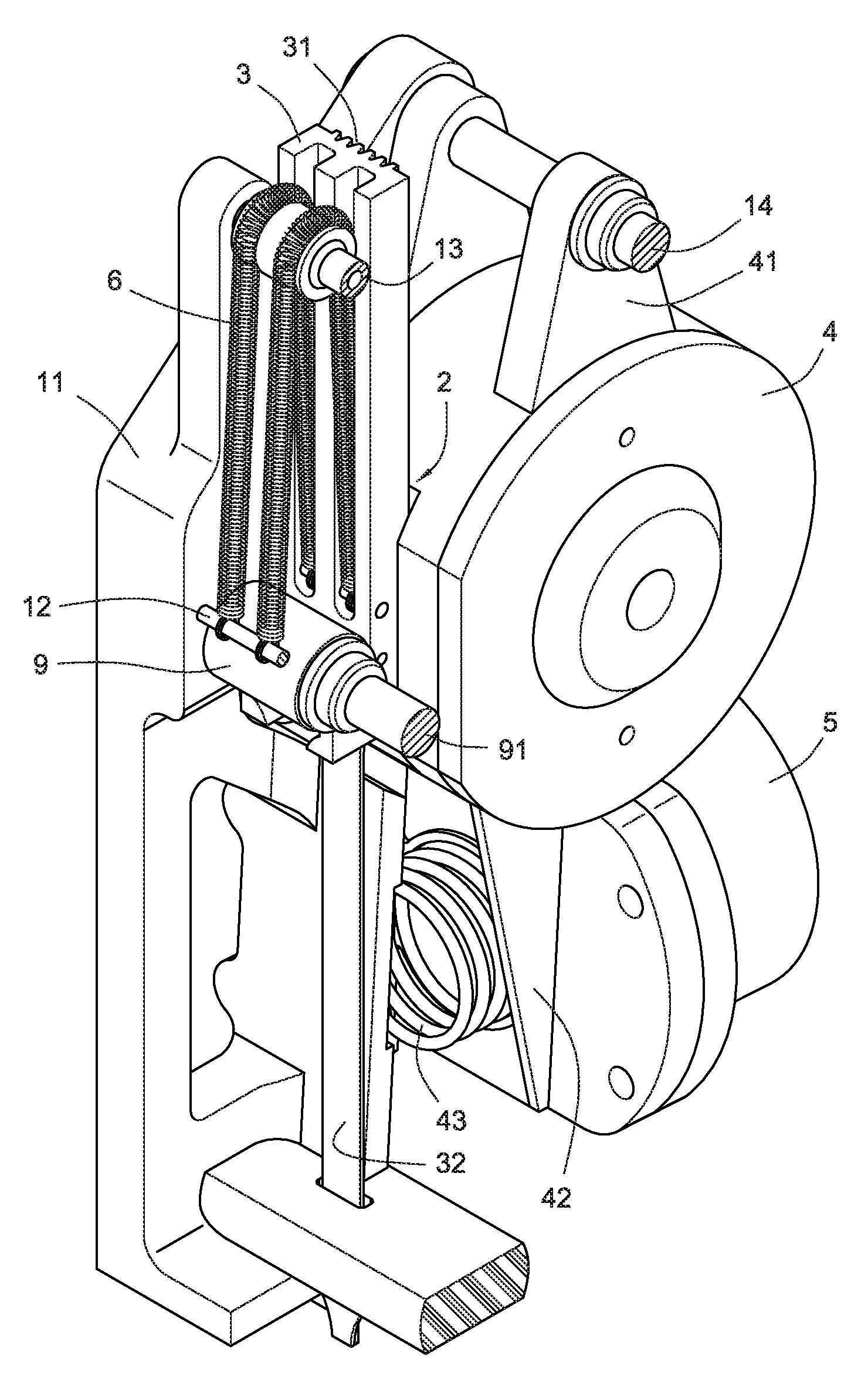
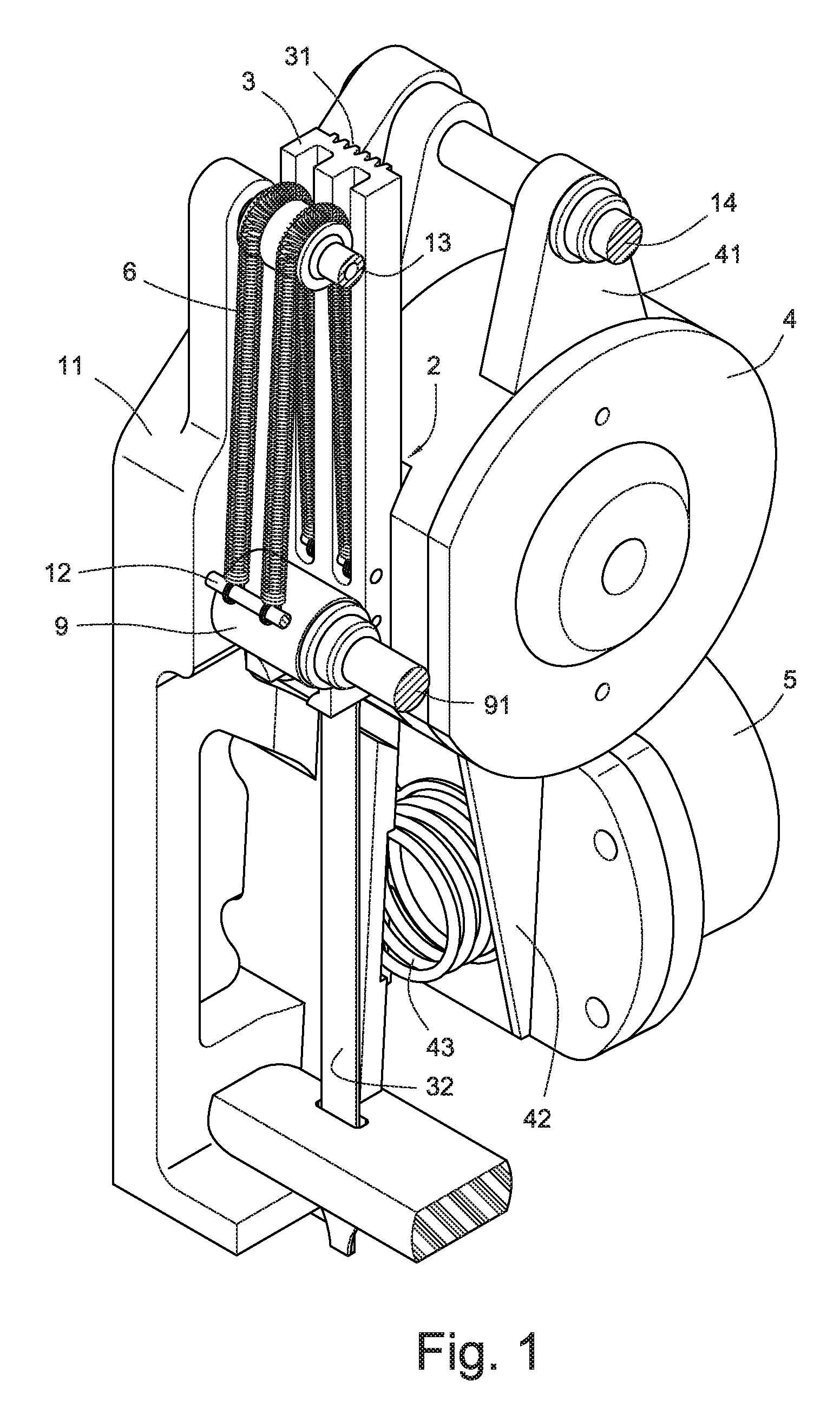
[0029]Referring to FIGS. 1 to 5, a clutch mechanism for transmission of kinetic energy in an electrical nail gun in accordance with a preferred embodiment of the present invention is shown. A suitable power source, such as the battery pack 10 for providing direct current, is received in a distal end of a housing 1. A supporting bracket 11 is formed on a head portion of the housing 1, for mounting a sliding base 3, a driver 2, a swing base 4, and an electric driver 5 thereon. A first switch 16 and a second switch 17 are formed on the housing 1. The first switch 16 is arranged on a bottom end of the housing 1 where a safety sliding rod 18 is capable of touching the first switch 16. The second switch 17 is located on an end side of the housing 1 where a trigger 19 mounted on the housing 1 can touch the second switch 17.

[0030]The sliding base 3, loading a spring 6, is slidably mounted in the housing 1 and arranged on an end side of a free roller 9. Substantially, at least an extension s...


PUM


Abstract

A clutch mechanism arranged in a housing of an electrical nail gun includes a sliding base, a driver driven by electricity, a swing base pivotally mounted on the housing, and an electric driver attached to the housing and being adjacent to an end side of the swing base. The sliding base is slidably disposed on an end of a free roller positioned in the housing, and the sliding base loads a spring and forms a hitting nail bar thereon. The driver has a motor and a flywheel driven by the motor, and the flywheel is configured to engage or disengage with / from the sliding base. The swing base is adjacent to the sliding base and the free roller and receives the driver therein. The electric driver has a rod member driven by electricity, and the rod member drives the swing base to swing to a first position where the flywheel meshes with the sliding base to thereby drive the sliding base to move downwards, and a second position where the flywheel disengages from the sliding base to thereby cause the sliding base to reposit. Thus, it is an advantage to improve service life and stability of the electrical nail gun.

Description

BACKGROUND OF THE INVENTION[0001]1. Field of the Invention[0002]The present invention relates to a swing-type clutch mechanism for an electrical nail gun, and more particularly to a clutch mechanism by which kinetic energy can be transmitted among a free roller, a sliding base and a flywheel.[0003]2. Description of Related Art[0004]An electrical nail gun is a type of tool used to hit nails into wood or some other kind of material. Usually, there is a battery pack or an AC electrical power source in a housing of the electrical nail gun to provide electrical power to a motor, thereby rotating the motor. A rotary kinetic energy of the motor is transformed into a linear kinetic energy by a transmission mechanism to drive a hitting nail bar to hit nails.[0005]Among a more advanced technology, many US patents, such as U.S. Pat. No. 6,607,111 and U.S. Pat. No. 6,669,072 and so on, teach a flywheel driven by a DC motor, a clutch assembly being capable of linear movement by traction of a wir...

Claims


Application Information

Patent Timeline
Patent Type & Authority Applications(United States)
IPC IPC(8): B25C1/06
CPCB25C1/06
Inventor LIANG, CHIA-SHENGTSENG, CHU-HSIANG
Owner ROBERT BOSCH TOOL
Why Eureka
Try Eureka