Combustion-powered nail gun

a nail gun and combustion chamber technology, applied in the direction of manufacturing tools, nailing tools, stapling tools, etc., can solve the problems of inability to perform “successive-shot driving” of conventional nail guns, and achieve the effect of preventing the combustion chamber frame from lowering

Inactive Publication Date: 2005-02-10
HITACHI KOKI CO LTD
View PDF25 Cites 34 Cited by
  • Summary
  • Abstract
  • Description
  • Claims
  • Application Information

AI Technical Summary

Benefits of technology

[0033]FIG. 7 is a partial cross-sectional view showing a combustion-powered nail gun according to a modification of the first embo...

Problems solved by technology

As such, it is impossible for the conventional nail gun to perform “successive-shot driving” in which the trigger switch is maintained in its ON position while successively driving a plurality of nails at different locations of the workpiece by repeatedly pushing and releasing the push lever toward and away fro...

Method used


Image

  • Combustion-powered nail gun
  • Combustion-powered nail gun
  • Combustion-powered nail gun

Examples


Embodiment Construction

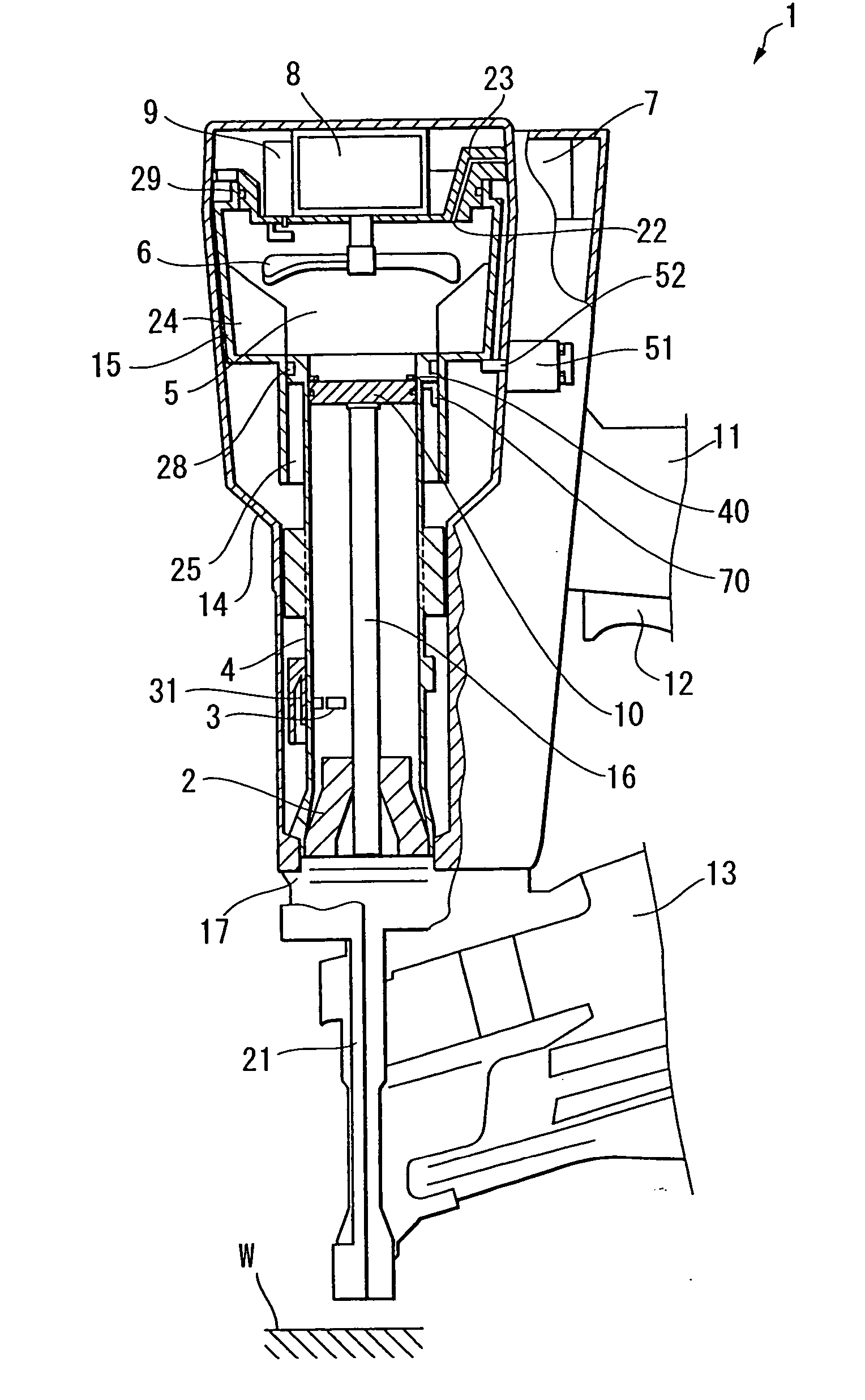
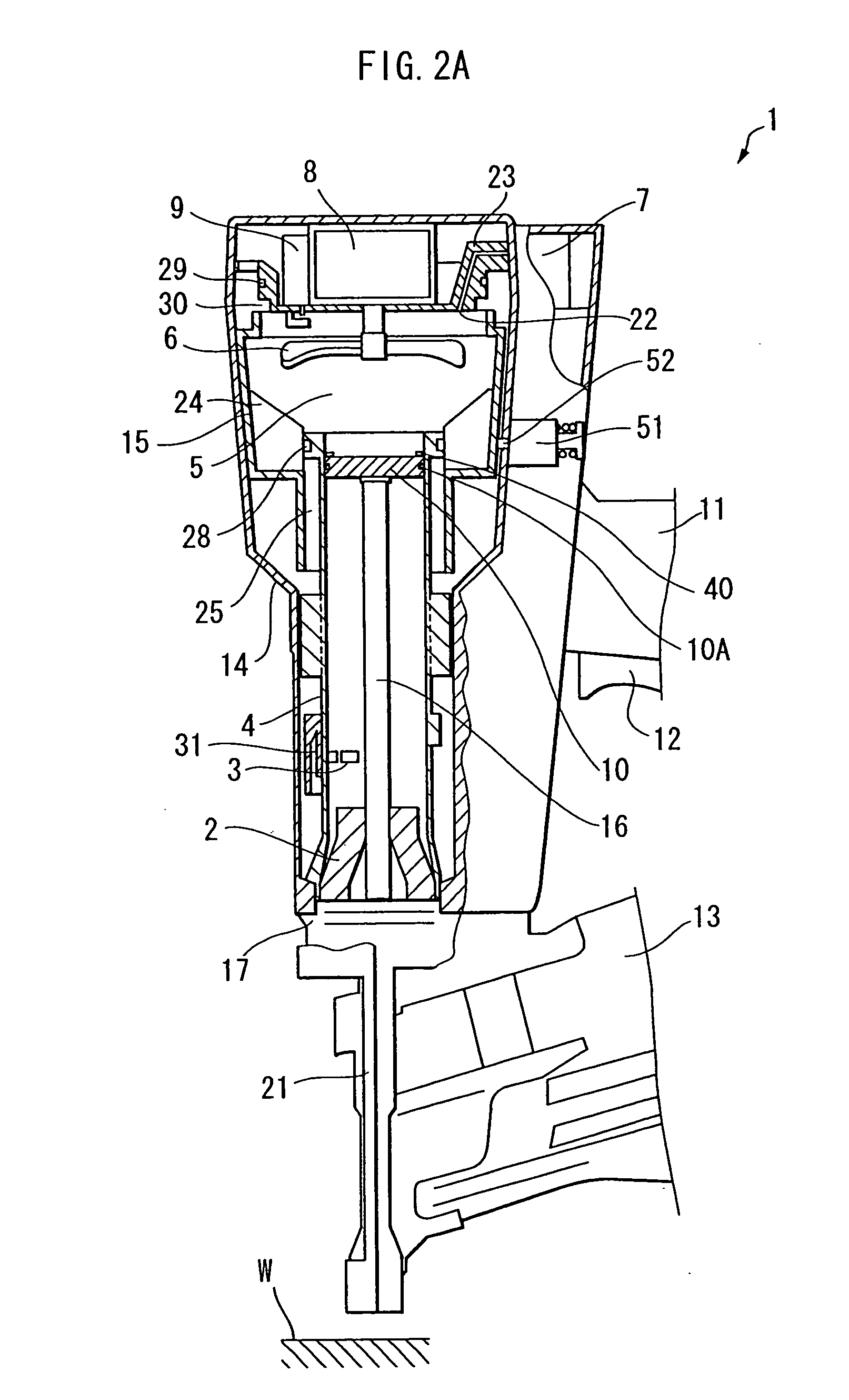
[0042] Referring to FIGS. 2A through 2C, a combustion-powered nail gun according to a preferred embodiment of the present invention will be described. In the following description, it is assumed that the nail gun is held in a state in which the nails are shot downward and the terms “upward”, “downward”, “upper”, “lower”, “above” and “below” and the like will be used throughout the description to describe various elements when the combustion-powered nail gun is held in such a state.

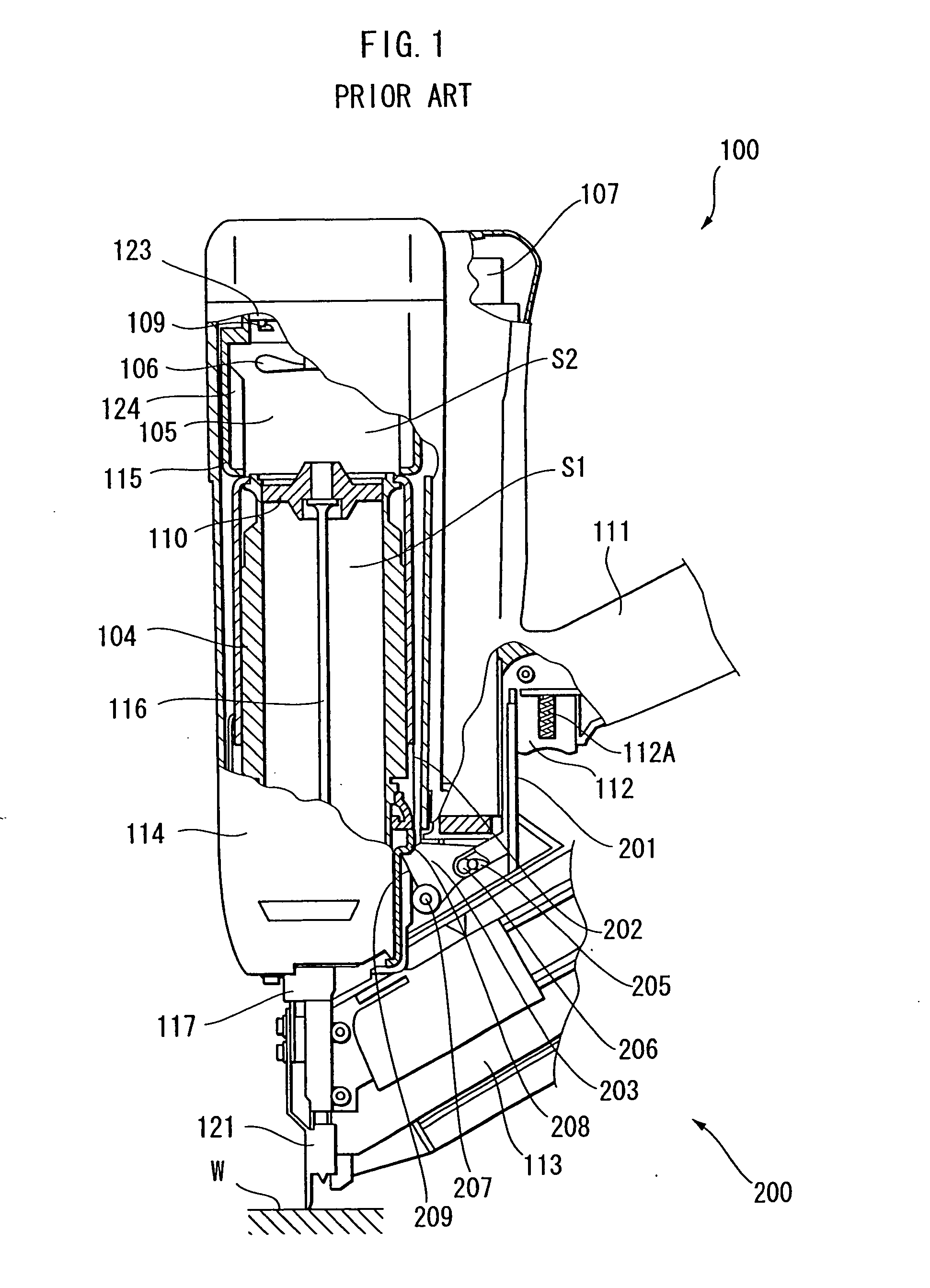
[0043] A structure of a combustion-powered nail gun 1 is almost the same as that of the conventional nail gun 100 shown in FIG. 1. The nail gun 1 includes a housing 14, a head cover 23, a combustion chamber frame 15, ribs 24, a cylinder 4, a piston 10, a driver blade 16, a handle 11, a trigger switch 12, a magazine 13, a tail cover 17, a push lever 21, a fan 6, a motor 8, a spark plug 9, and fuel canister 7. All these elements are similar to those of the conventional nail gun 100 shown in FIG. 1. The comb...


PUM

PropertyMeasurementUnit
Timeaaaaaaaaaa

Abstract

A combustion-powered nail gun drives nails into a workpiece when both a head switch and a trigger switch are turned ON while a safety switch is turned ON. The nail driving operation cannot be performed if the safety switch is not ON even if both the head switch and the trigger switch are ON. The head switch is turned ON when a push lever is urged against the workpiece. Fuel/air mixture in a combustion chamber is ignited when the head switch and the trigger switch are turned ON irrespective of an order in which the head switch and the trigger switch are turned ON, whereby “successive-shot driving” can be performed in which the trigger switch is maintained in its ON position while successively driving a plurality of nails at different locations of the workpiece by repeatedly pushing and releasing the push lever toward and away from the workpiece.

Description

CROSS-REFERENCE TO RELATED APPLICATION [0001] This is a Continuation-In-Part of application Ser. No. 10 / 637,571 filed Aug. 11, 2003. The entire disclosure of the prior application is hereby incorporated by reference herein in its entirety.BACKGROUND OF THE INVENTION [0002] 1. Field of the Invention [0003] The present invention relates to a combustion-powered nail gun that generates drive force by igniting a fuel / air mixture to drive a fastener such as a nail into a workpiece. [0004] 2. Description of the Related Art [0005] U.S. Pat. Nos. 4,403,722, 4,483,280(Re.32,452), 4,483,473, and 4,483,474 disclose combustion-powered tool assemblies. FIG. 1 schematically shows configuration of a conventional combustion-powered nail gun 100 similar to that disclosed in these U.S. Patents. The nail gun 100 includes a housing 114 to which a handle 111, a tail cover 117, a push lever 121, and a magazine 113 are disposed. [0006] The housing 114 accommodates therein a head cover 123, a combustion cha...

Claims


Application Information

Patent Timeline
IPC IPC(8): B25C1/14
CPCB25C1/08B25C1/008
Inventor SHIMA, YUKIHIROOHMORI, YASUKI
Owner HITACHI KOKI CO LTD
Why Eureka
Try Eureka