Nailing Gun Trigger Safety Device and Nailing Gun Provided with the Same

a safety device and trigger technology, applied in the field of trigger safety devices, can solve the problems of increased production cost of nailing guns, increased volume and weight of nailing guns, and only suitable structure of nailing guns, etc., and achieves the effects of simple structure, convenient use and good safety

Inactive Publication Date: 2011-03-10
TAIZHOU DAJIANG IND
View PDF7 Cites 35 Cited by
  • Summary
  • Abstract
  • Description
  • Claims
  • Application Information

AI Technical Summary

Benefits of technology

[0004]The technical problem required to be solved in the invention lies in overcoming the deficiencies in the prior art, and providing A nailing gun trigger safety device and a nailing gun provided with the same with simple structure, convenient use and good safety.
[0016]The contact-jacking mechanism 20 is then pressed, and since the transmission mechanism 40 is obstructed by the air pressure of the switch, the pivot 34 of the fork 32 neutralizes the resistance of the elastic member 33 to move backwards inside the slide slot of the bracket 31, neither poking the transmission mechanism 40 nor pushing the pressing sheet 51 of the switch to cause percussion.
[0017]The nailing gun equipped with the safe device according to the invention can achieve percussion only according to correct operation sequence, enhancing the safety of the nailing gun.
[0018]Compared with the prior art, a nailing gun trigger safety device and a nailing gun equipped with the device according to the invention at least have the following advantages:
[0019]1. A nailing gun trigger safety device provided by the invention is provided with a poking device and a transmission device between the contact-jacking mechanism and the trigger mechanism, such a mechanical structure enables the nailing gun trigger safety device to simple structure, thereby reducing the manufacturing cost of the nailing gun.
[0020]2. A nailing gun trigger safety device provided by the invention adopts the mechanical structure, which diminishes the occupied space of the nailing gun trigger safety device and the volume of the nailing gun, as well as reduces the weight of the nailing gun.

Problems solved by technology

The nailing gun safety device described in the patent realizes the linkage between the top support device and the pneumatic safety device through the driving device in order to achieve the purpose of protecting users, however, the pneumatic safety device with complex structure of the air circuit and quite high requirement on processing precision needs to be connected with a high pressure air chamber and shunts high pressure air, so the production cost of the nailing gun is increased; in addition, the pneumatic safety device has larger volume and occupied space, increasing the volume and the weight of the entire nailing gun.
Nevertheless, the structure of this nailing gun is apparently only suitable for electric nailing guns, not for pneumatic nailing guns.
Furthermore, such a nailing gun cannot differentiate correct operation sequence, which leads to the fact that the percussion of the nailing gun occurs only if the push rod is pressed and the trigger is pulled, causing danger in some cases.

Method used


Image

  • Nailing Gun Trigger Safety Device and Nailing Gun Provided with the Same
  • Nailing Gun Trigger Safety Device and Nailing Gun Provided with the Same
  • Nailing Gun Trigger Safety Device and Nailing Gun Provided with the Same

Examples


Embodiment Construction

[0029]Detailed description is made to the embodiments of the invention, and examples of the embodiments are shown in the attached drawings, with the same mark number always representing the same element. The explanation of the invention is given below through the embodiments described with reference to the attached drawings, and the embodiments, which are exemplary, cannot be explained to the limitation for the invention.

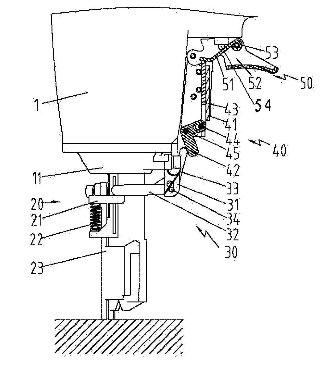
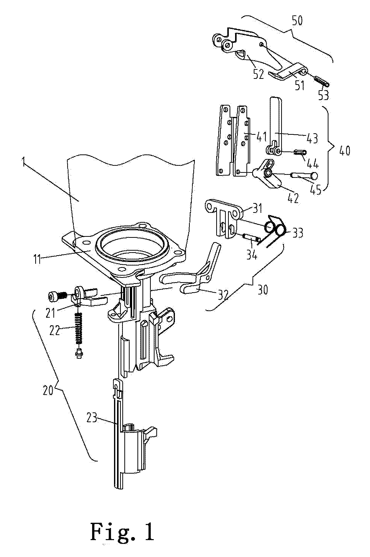
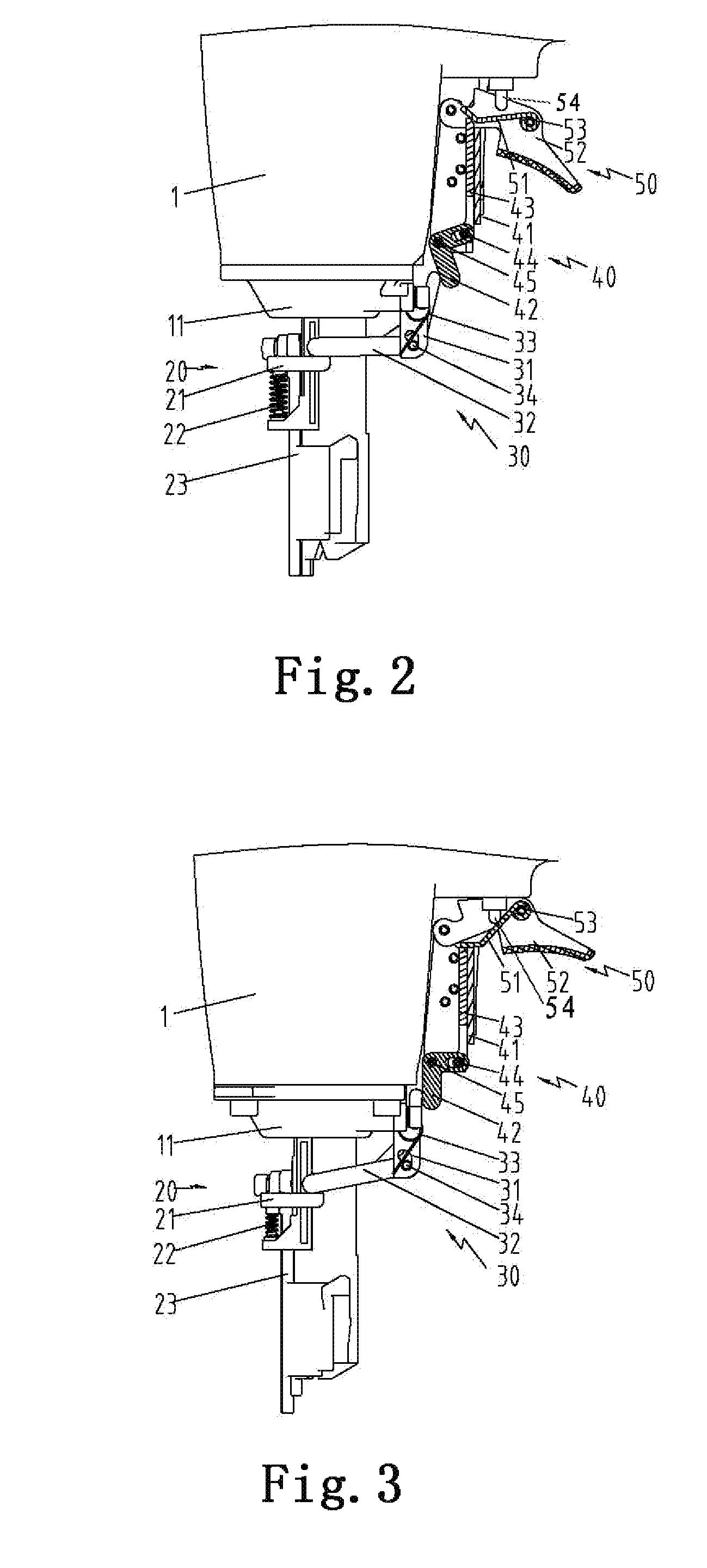
[0030]With reference to the FIG. 1, the nailing gun trigger safety device is arranged on the nailing gun body 1 and is linked with the trigger mechanism 50, what needs to explain is that the linkage herein means the junction of the safe device and the trigger mechanism 50 can move as the trigger mechanism 50 moves during the movement of the trigger, so as to drive the entire nailing gun trigger safety device to move. For example, the trigger mechanism comprises a trigger 52, a pressing sheet 51, a pivot 53, and an air needle 54 for starting up the nailing gun percus...


PUM

PropertyMeasurementUnit
pressureaaaaaaaaaa
volumeaaaaaaaaaa
weightaaaaaaaaaa

Abstract

A nailing gun trigger safety device and a nailing gun provided with the same are disclosed. Said nailing gun safety device is provided on the nailing gun body and interconnects with a trigger mechanism. Said nailing gun trigger safety device includes a contact-jacking mechanism and an poking mechanism interconnected with the contact-jacking mechanism. Said contact-jacking mechanism is slidably mounted on the distal end of the nailing body. Said poking mechanism interconnects with the contact-jacking mechanism. Said nailing gun trigger safety device further includes a transmission mechanism interconnected with the trigger mechanism and said transmission mechanism interconnects with said poking mechanism and the trigger mechanism respectively. Such a mechanical structure makes the structure of the nailing gun trigger safety device simple and reduces the manufacture cost.

Description

FIELD OF THE INVENTION[0001]The invention relates to a trigger safety device, more particularly to a nailing gun equipped with the device.BACKGROUND OF THE INVENTION[0002]Owing to convenient carrying and usage, small power tools have become indispensible to various projects such as construction, civil engineering, decoration, etc. Increasing importance is attached to the safety of the power tools in the usage process thereof. In order to avoid that accidental trigger of the nailing gun in the projects accidentally injures people or objects, a trigger safety device is usually required to be arranged on the nailing gun to protect users. In the utility model patent of China (Patent Number: 200620055098.1, Publication Day Feb. 21, 2007), a nailing gun safe device is disclosed, which comprises a pneumatic safety device, a top support device and a driving device, wherein the pneumatic safety device comprises a valve seat and an air valve arranged inside the valve seat and capable of slide...

Claims


Application Information

Patent Timeline
Patent Type & Authority Applications(United States)
IPC IPC(8): B25C1/00
CPCB25C1/008
Inventor YANG, MINGJUNWU, QICHENG
Owner TAIZHOU DAJIANG IND
Why Eureka
Try Eureka