
Locking fastener assembly

a technology of fasteners and assemblies, applied in the direction of threaded fasteners, screws, washers, etc., can solve the problems of reducing the strength of nuts, and using an extra componen

Inactive Publication Date: 2007-06-05
MAC LEAN FOGG CO
View PDF47 Cites 27 Cited by
  • Summary
  • Abstract
  • Description
  • Claims
  • Application Information

AI Technical Summary

Benefits of technology

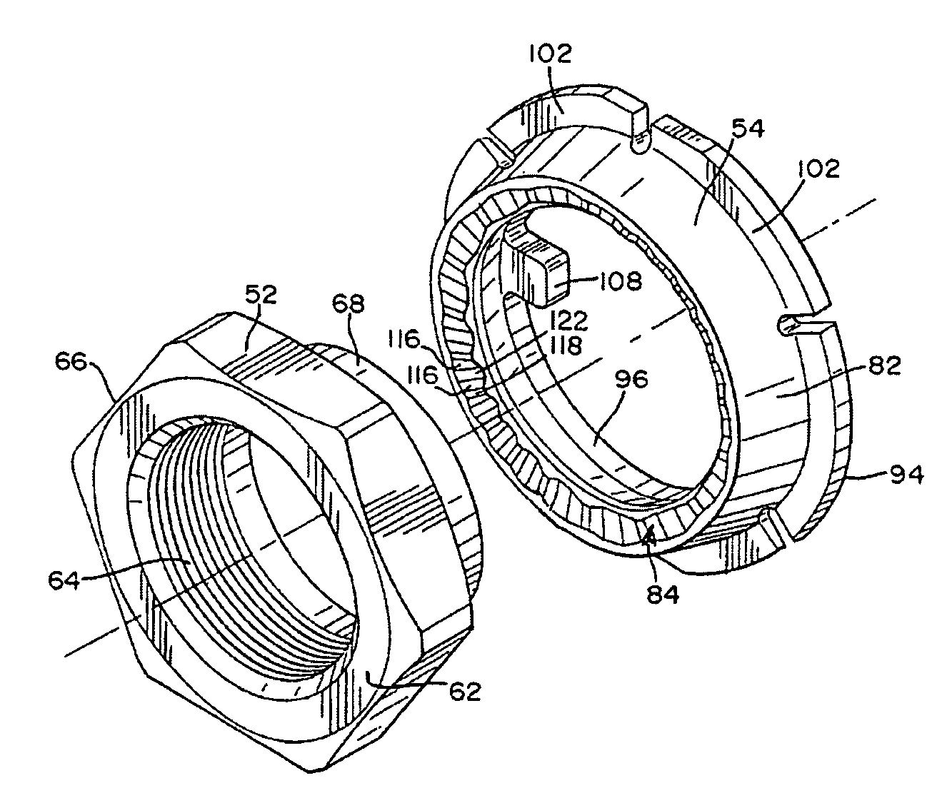
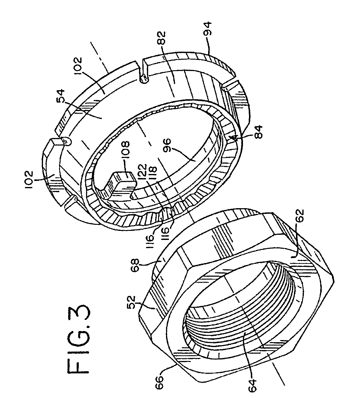
[0023]Depending from the nut body is a unitarily formed annular skirt. The skirt is adapted to extend axially into the generally cylindrical body of the washer and then be formed outwardly under an undercut shoulder within the washer body to loosely, but securely, hold the washer and nut together.
[0027]In locked relationship, the spherically convex plateau surfaces in the load bearing surface of the nut seat flush against corresponding spherically concave valley surfaces in the load bearing surface of the washer. Also, the convex inclined leading bearing faces on the nut seat flush against the concave inclined trailing bearing faces of the washer and prevent the nut from backing off.

Problems solved by technology

The axle bearing nut must be set in precisely the proper position on the spindle to apply end loading on the bearing races sufficient to avoid excessive play in the bearings but insufficient to overload them, the result of either being possible bearing failure or even loss of a wheel.
The disadvantages of these assemblies are numerous.
They include the necessity of carefully locating a hole through the axle spindle, of using an extra component, of reduced nut strength, of relatively long installation time and of the difficulties encountered in fine tuning the preload on the bearing races.
However, its design focuses on limiting end play, not maintaining a constant pre-load.
Disassembly is even difficult.
Complete disengagement in service is highly unlikely.

Method used


Image

  • Locking fastener assembly
  • Locking fastener assembly
  • Locking fastener assembly

Examples


Embodiment Construction

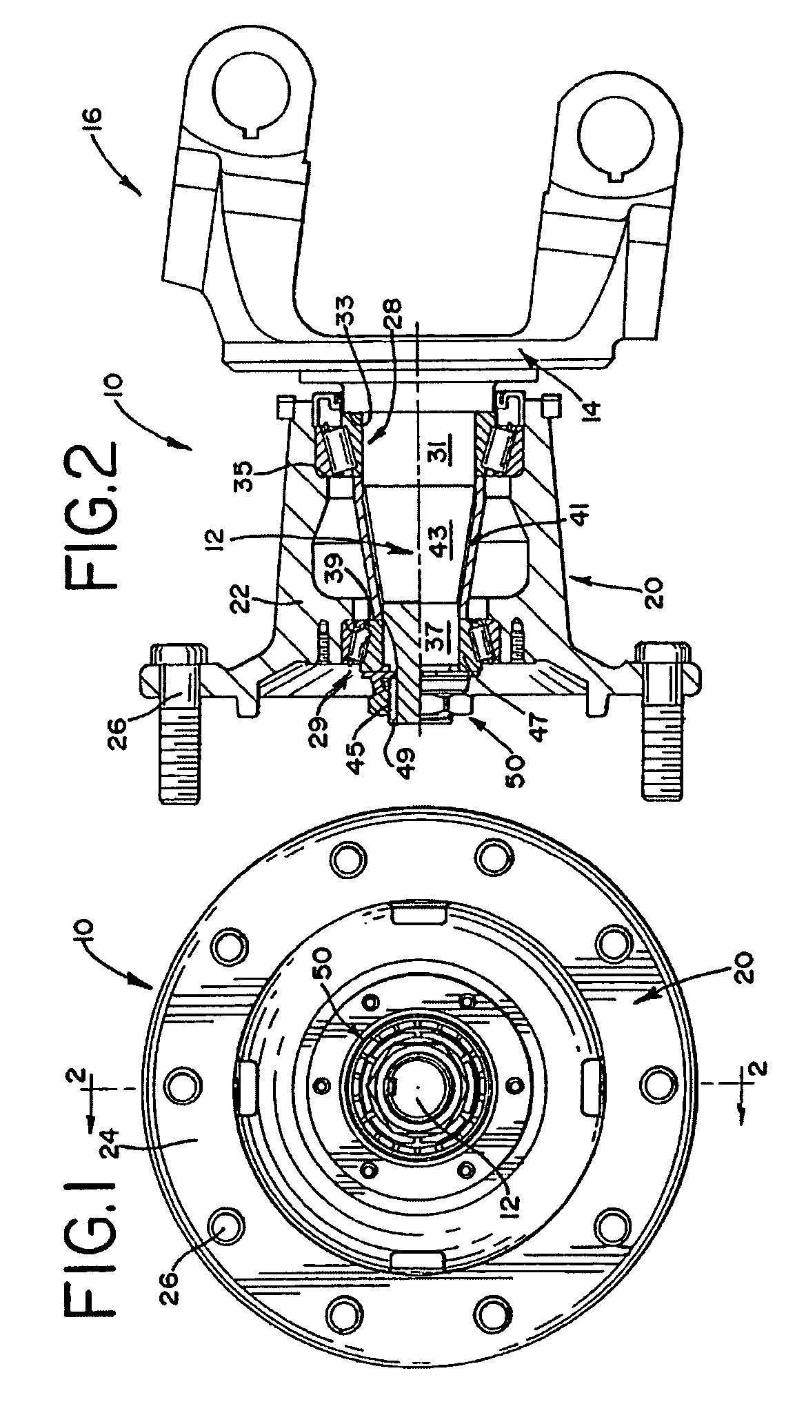
[0039]Referring to the drawings, and particularly to FIGS. 1 and 2, an axle assembly for an automotive vehicle is shown generally at 10. The axle assembly 10 includes a spindle 12 which extends horizontally from a vertically oriented plate 14. The plate 14 forms the outer face of a fitting 16 which is mounted in a conventional manner on the frame (not shown) of a vehicle.

[0040]Seated for rotation on the spindle 12 is a wheel hub 20. The wheel hub 20 includes a generally cylindrical body 22 formed unitarily with a radially extending flange 24. A plurality of studs 26 extend axially from the flange 24 near its periphery. The studs 26 are employed in a conventional manner to mount a wheel (not shown) on the wheel hub 20.

[0041]The wheel hub 20 is seated on the spindle 12 on an inner roller bearing assembly 28 and an outer roller bearing assembly 29. The inner bearing assembly 28 is located on a cylindrical inner section 31 of the spindle 12 and is retained between a shoulder 33 on the s...


PUM


Abstract

A locking fastener assembly comprising a nut and a washer. The nut and washer each have opposed load bearing surfaces which include a series of annularly extending, slightly inclined faces forming shallow undulations around each surface. The load bearing surface on the nut is generally spherically convex and the load bearing surface on the washer is generally spherically concave. The nut rotates as it is installed while the washer is prevented from rotating so that the undulating bearing surface on the nut slides over the undulating bearing surface on the washer against ever increasing resistance until the assembly is properly seated and the nut is effectively prevented from counter-rotating by interference between opposed, inclined faces. A concave clamping surface is formed on the outer end of the washer on a radially extending flange. The flange flexes when the assembly is installed and resiliently urges the washer against the nut.

Description

[0001]This is a continuation of application Ser. No. 09 / 933,312 filed Aug. 20, 2001 now U.S. Pat. No. 6,749,386FIELD OF THE INVENTION[0002]This invention relates generally to threaded fasteners. It relates particularly to locking fasteners of the type employing a threaded nut and a locking washer.BACKGROUND OF THE INVENTION[0003]A locking fastener or locking fastener assembly is employed to prevent loosening of a threaded fastener element in a fastener joint. There are numerous types of joints in which locking fasteners or fastener assemblies are not only desirable but necessary to prevent a nut from loosening. One such application is in the axle and wheel nut assembly of a motor vehicle or the like.[0004]In a typical axle and wheel nut assembly, the hub is supported on a spindle by axle bearings which permit the hub, and thus a vehicle wheel, to rotate on the spindle. An axle bearing nut is threaded onto the free end of the spindle and holds the axle bearings and bearing races toge...

Claims


Application Information

Patent Timeline
IPC IPC(8): F16B39/24F16B37/00F16B39/282F16B43/00F16C25/06
CPCF16B39/24F16B39/282F16B43/00F16C25/06F16C19/548F16C2326/02F16B41/002
Inventor HARRIS, DAVID A.
Owner MAC LEAN FOGG CO
Learn More