
Sliding door reinforced frame header with movable cover

a technology of sliding door and header, which is applied in the direction of wing accessories, curtain suspension devices, manufacturing tools, etc., can solve the problems of nettlesome removal of controls and motor operators, lack of ease with which they may be installed in the header, etc., and achieve the effect of improving the header or overhead support structur

Active Publication Date: 2007-06-12
OVERHEAD DOOR
View PDF15 Cites 29 Cited by
  • Summary
  • Abstract
  • Description
  • Claims
  • Application Information

AI Technical Summary

Benefits of technology

[0004]The present invention provides an improved motorized sliding door including, in particular, an improved header or overhead support structure for such doors wherein such support structure is strengthened to support one or more sliding door panels. The header is also adapted to support a removable frame which supports a door drive motor and door controls. The invention also contemplates an improved access door or cover which provides ease of access to the operator motor and the controls.
[0006]Still further, the present invention provides an improved arrangement of a so-called torsion bar assembly for supporting a door panel to breakaway from its normal working position in an emergency and whereby the door panel may be restored to its original working position without requiring refitting the door. In this regard the door is at least partially supported by the torsion bar assembly which includes an improved adjustment feature which provides for ease of adjustment to minimize or eliminate any sag in the door panel when it moves from its normal working position to a swung open position.

Problems solved by technology

In this regard the lack of ease with which the controls and the motor operator may be installed in and removed from the header has also been a somewhat nettlesome problem.

Method used


Image

  • Sliding door reinforced frame header with movable cover
  • Sliding door reinforced frame header with movable cover
  • Sliding door reinforced frame header with movable cover

Examples


Embodiment Construction

[0017]In the description which follows like parts are marked throughout the specification and drawings with the same reference numerals, respectively. The drawings are not necessarily to scale and certain features may be shown in somewhat schematic or generalized form in the interest of clarity and conciseness.

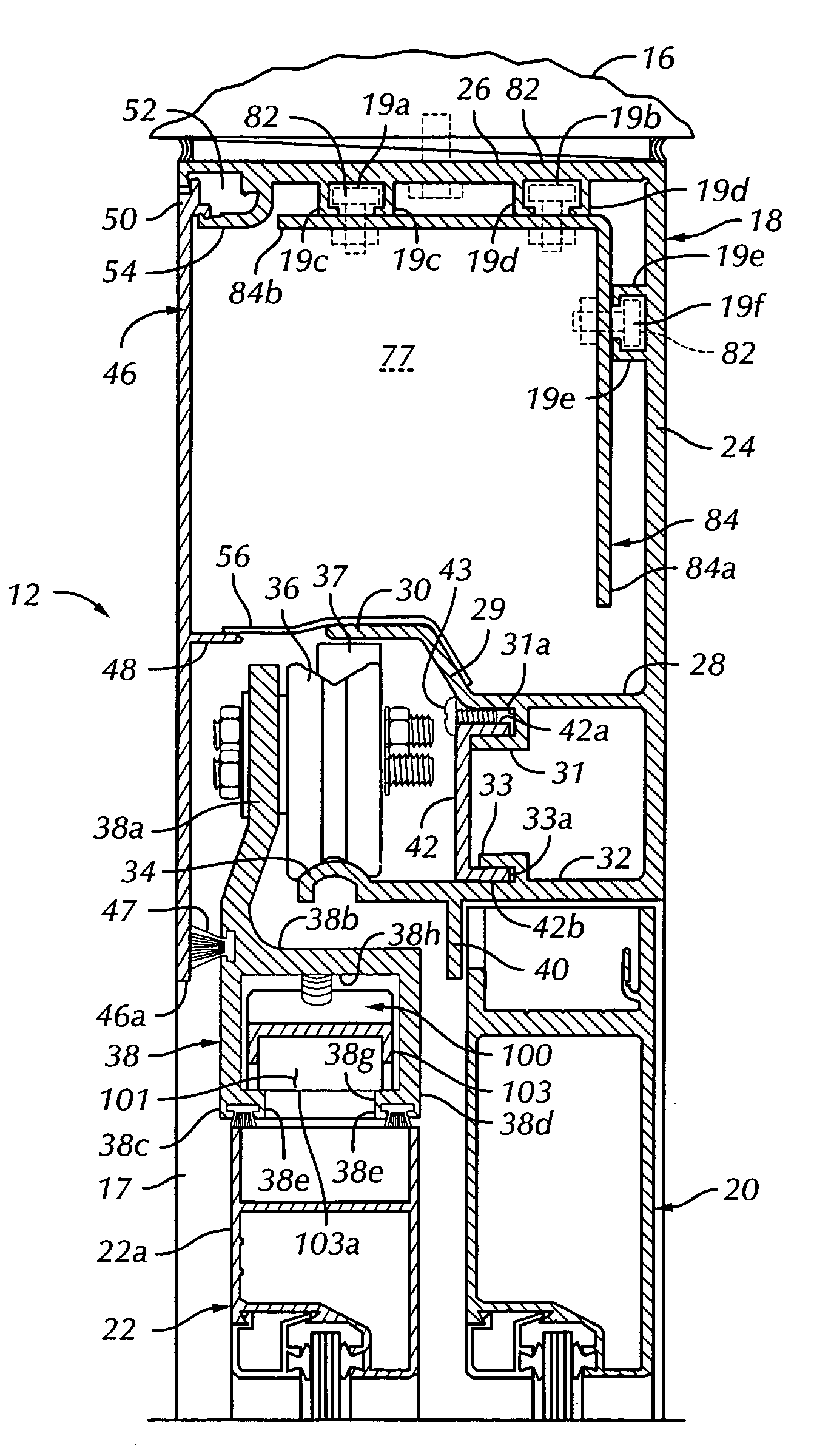
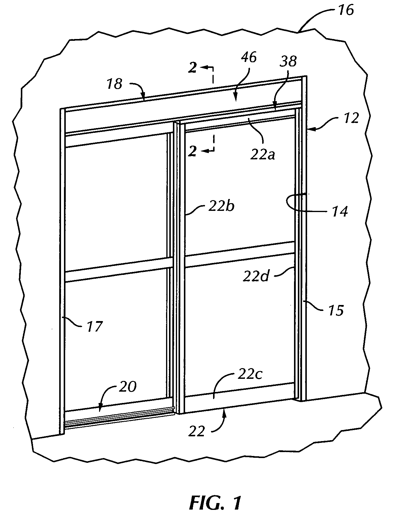
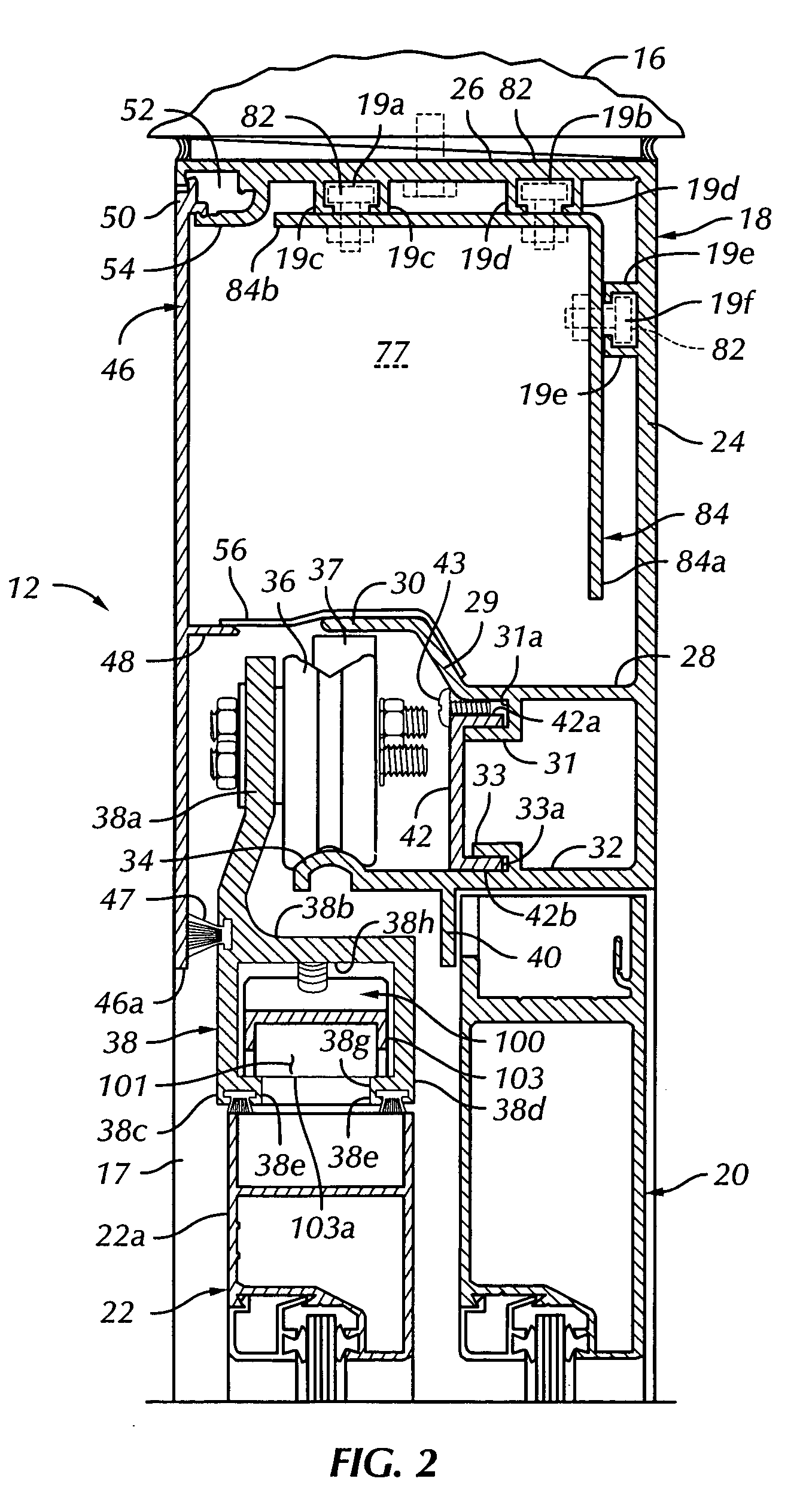
[0018]Referring to FIG. 1, there is illustrated an exemplary embodiment of a sliding door, including improvements in accordance with the present invention, which door is generally designated by the numeral 12. The door 12 is disposed in an opening 14 in a wall 16 and is supported by a frame including spaced apart, vertically extending frame members 15 and 17 and a transverse horizontal frame member or header 18. The aforementioned frame, including the header 18, supports a stationary panel 20 and a moveable, sliding door panel 22. Panel 22 is supported substantially by the header 18 and is moveable between the closed position shown and an open position overlying the panel 20 i...


PUM


Abstract

A sliding door includes a frame comprising an elongated header member having a topwall, a backwall, an intermediate wall and a bottom wall. The bottom wall and intermediate wall are engageable with sliding door panel support rollers and the bottom wall and intermediate wall are interconnected by a separate support member to distribute door panel loads between such walls. A movable cover is attached to the header member by a hinge part including spaced apart flanges and projections co-operable with projections on the header member to support the cover in open and closed positions. The door operator is supported in the header member by a single angle-shaped frame member supporting a power supply, a controller and a door operator motor. An adjustable torsion bar assembly supports the door panel against sagging.

Description

BACKGROUND OF THE INVENTION[0001]In the art of motorized sliding doors, there is a continuing need for improvements in the door support structure, including the so-called the header rail structure which is adapted to support one or more sliding door panels, motor controls and the door operator and motor. Improvements in access to this support structure for adjusting and servicing the controls and the operator mechanism have also been sought. In this regard the lack of ease with which the controls and the motor operator may be installed in and removed from the header has also been a somewhat nettlesome problem.[0002]Still further improvements which have been sought in the art of sliding doors include improvements in a so-called torsion bar assembly which supports the sliding door panel or panels in the situation wherein a panel is of the breakaway type which may be swung open in an emergency.[0003]The desire and need for improvements in sliding doors with regard to the above-noted fe...

Claims


Application Information

Patent Timeline
Patent Type & Authority Patents(United States)
IPC IPC(8): E05D15/06E05D15/48E05F1/10E05F15/14
CPCE05D15/0626E05F15/643E05F1/1033E05D15/48E05D2015/586E05Y2201/10E05Y2201/11E05Y2600/10E05Y2600/46E05Y2800/16E05Y2800/25E05Y2800/746E05Y2900/132Y10T16/373Y10T16/5362Y10T16/379
Inventor ROMERO, FEDERICOLILES, JR., WILLIAM S.
Owner OVERHEAD DOOR
Learn More