One-way valve for a side pocket mandrel of a gas lift system

a technology of gas lift system and side pocket mandrel, which is applied in the direction of directional drilling, borehole/well accessories, construction, etc., can solve the problems of moving parts being susceptible to failure, sucker rod string cannot be placed through the subsurface safety valve, and disadvantageous moving parts

Active Publication Date: 2007-06-12
WEATHERFORD TECH HLDG LLC
View PDF21 Cites 33 Cited by
  • Summary
  • Abstract
  • Description
  • Claims
  • Application Information

AI Technical Summary

Benefits of technology

[0025]In another aspect, embodiments of the present invention generally provide a method of preventing fluid flow from a bore of production tubing to an annulus between an outer diameter of the production tubing and a wellbore, comprising providing the production tubing having a side pocket mandrel therein in the wellbore, the side pocket mandrel having a side pocket with at least one first valve member therein and at least one second valve member; introducing a gaseous fluid into the annulus; flowing the gaseous fluid from the annulus into the bore through the side pocket mandrel; and preventing flow of a second fluid from the bore into the annulus using at least one of the valve members. In yet another aspect, embodiments of the present invention include a method of preventing fluid from flowing from a bore of production tubing disposed within a wellbore into an annulus between an outer diameter of the production tubing and the wellbore, comprising providing the production tubing within the wellbore, the production tubing comprising a side pocket mandrel having a side pocket therein, and at least two one-way valves disposed within the side pocket; using at least one of the one-way valves to prevent fluid flow in a first direction from the bore to the annulus; and allowing flow of a gaseous fluid in a second direction from the annulus into the bore.

Problems solved by technology

Often, pressure within the wellbore is insufficient to cause the production fluid to naturally rise through the production tubing to the surface of the wellbore.
In some applications, the moving parts are disadvantageous.
When a subsurface safety valve is employed within the wellbore, such as within an offshore well, a sucker rod string cannot be placed through the subsurface safety valve.
Additionally, moving parts are susceptible to failure or damage, potentially causing the sucker rod lifting systems to become inoperable.
First, the gas lift valves typically require maintenance, repair, or replacement, for example if the valve is leaking fluid flow into the annulus from the production tubing bore.
Second, altering the pressure settings of the gas lift valves, which is often required during a gas lift operation, requires access to the gas lift valves by the operator.
Removing the entire production tubing from the wellbore is costly and inefficient; therefore, wireline-retrievable gas lift systems are often the preferred type of gas lift system, especially when the gas lift system is used offshore or in remote locations where rig interventions are expensive.
Moreover, the gas lift valve may fail or leak during the gas lift operation.
Removal of the gas lift valve from the production tubing and / or failing or leaking of the gas lift valve are problematic because the gas lift valve is no longer present within the side pocket mandrel or is no longer effective to prevent fluid flow from the production tubing into the annulus.
The presence of production fluid in the annulus is problematic for several reasons.
First, the production fluid is corrosive to the casing surrounding the production tubing string and may therefore cause corrosion damage to the casing.
Second, the production fluid existing within the annulus increases the fluid pressure present within the annulus, possibly increasing to sufficient pressure levels to cause damage to the casing surrounding the production tubing string.
Damaging the casing could cause the production fluid to leak back into the formation through holes in the casing, resulting in loss of valuable production fluid as well as becoming an environmental hazard.
Repairing this damage to the casing is very expensive, especially in the form of loss of production during the repair time, as the production tubing string and other gas lift equipment must be removed from the wellbore and a casing section or casing patch must be re-installed within the wellbore over the damaged portion of the casing.
Additionally, the presence of production fluid in annulus is problematic because, even without resulting damage to the casing, time-consuming preparatory activities must be carried out before the gas lift operation may resume after re-installing the gas lift valves within the side pockets of the side pocket mandrels.
One especially time-consuming operation which must be accomplished prior to resuming the gas lift operation involves unloading the production fluid present within the annulus from the wellbore.
Unloading the well, if production fluid is present within the production tubing as well as within the annulus, often takes twelve hours or more every time the gas lift valves must be removed from the production tubing.
Unloading the production fluid from the annulus typically consumes 8–9 hours of that unloading time.
This time required to unload the annulus prior to any further gas lift operation wastes valuable production time, decreasing the profitability of the well.

Method used


Image

  • One-way valve for a side pocket mandrel of a gas lift system
  • One-way valve for a side pocket mandrel of a gas lift system
  • One-way valve for a side pocket mandrel of a gas lift system

Examples


Embodiment Construction

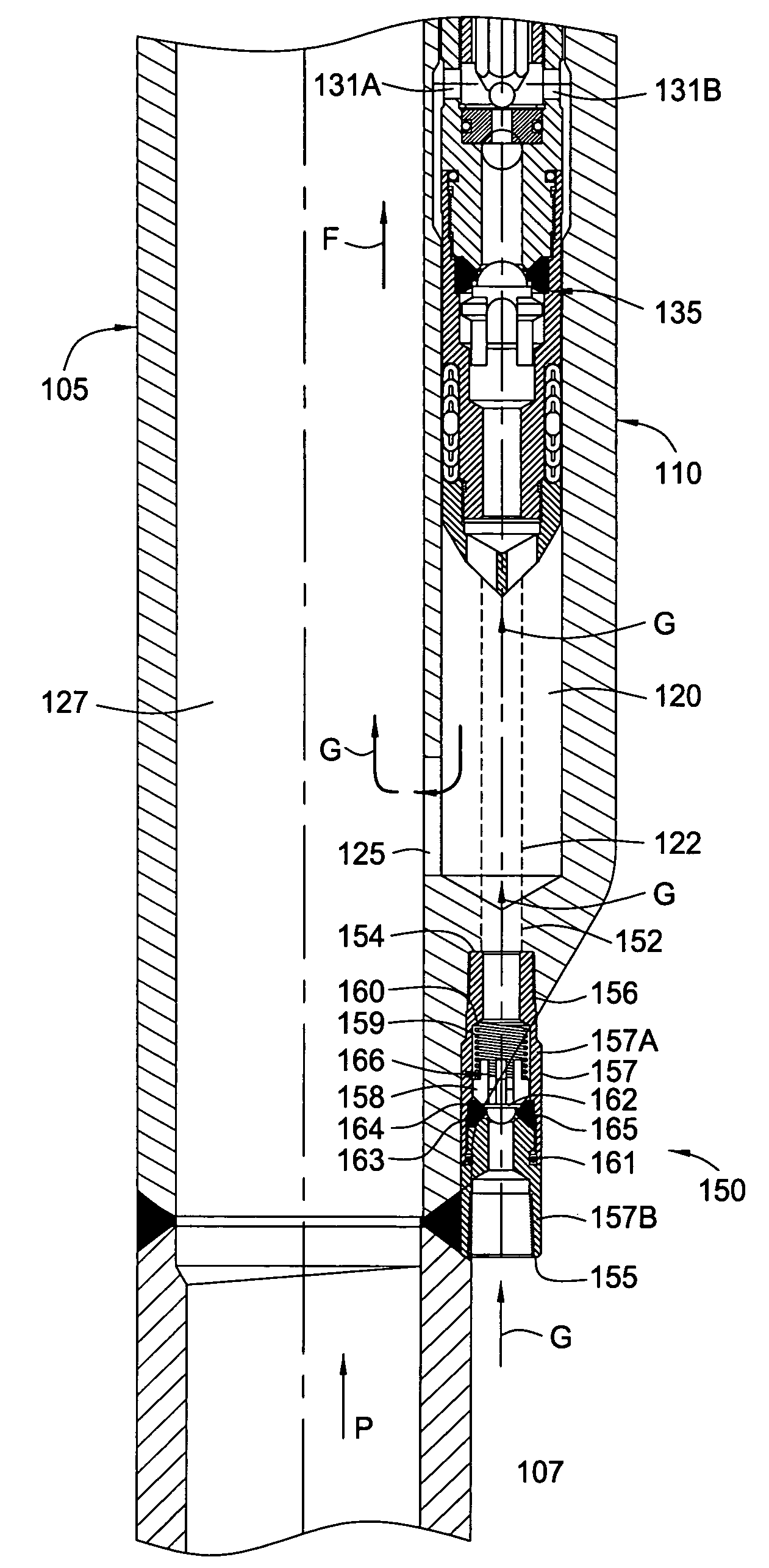
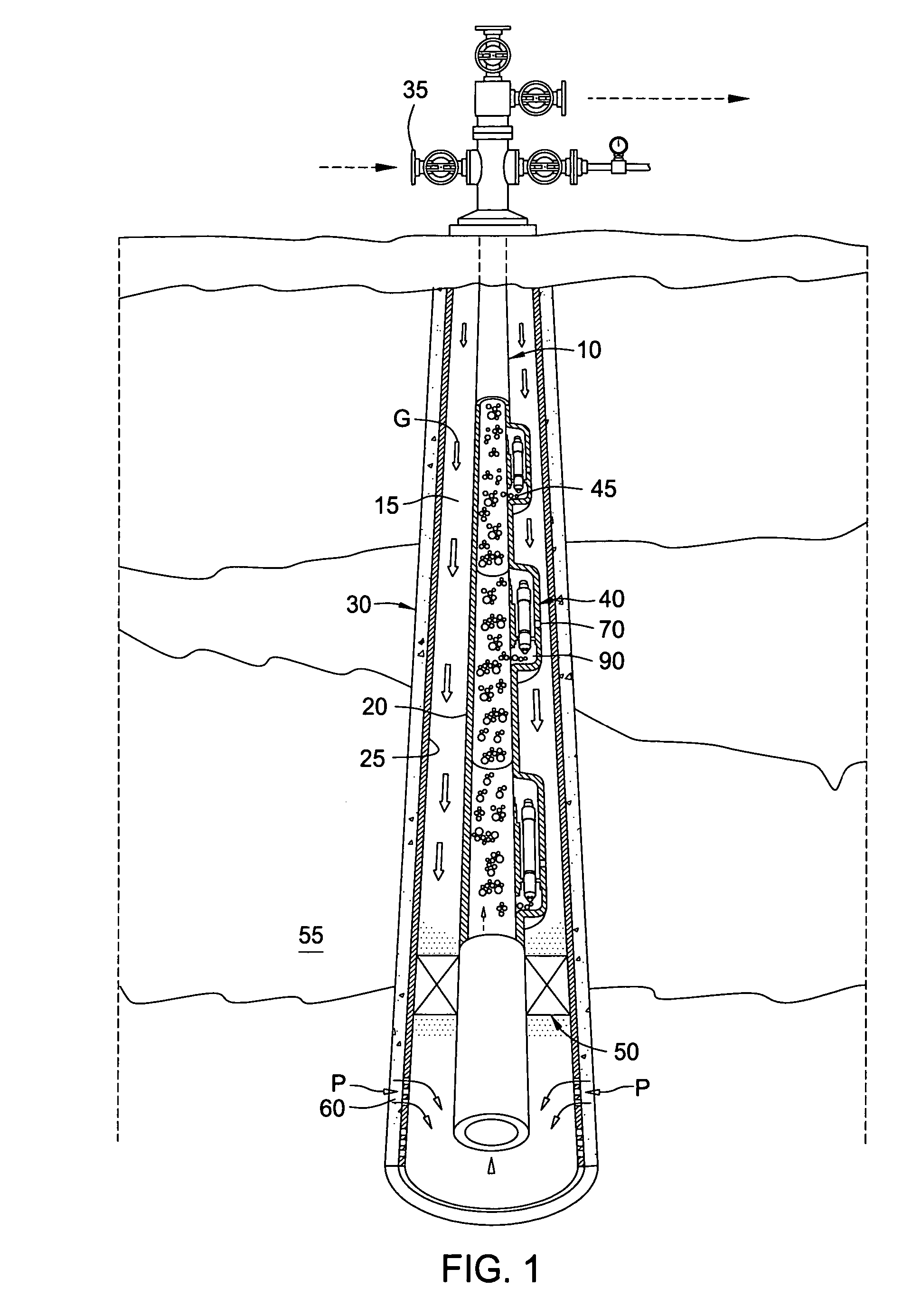
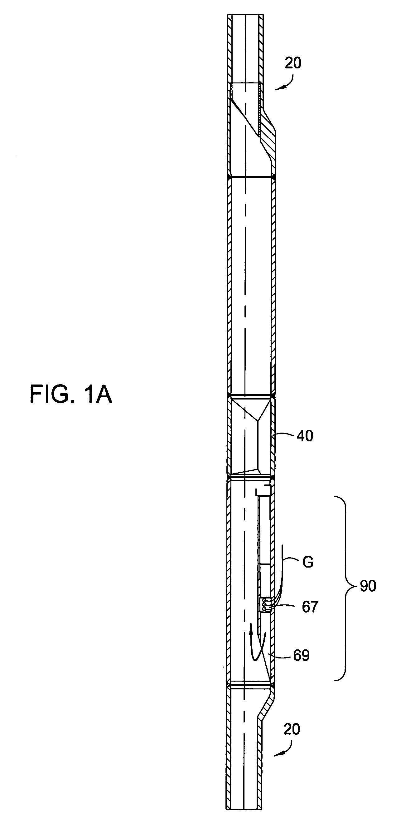
[0036]Embodiments of the present invention include a gas lift system having one or more one-way valves present within one or more side pocket mandrels in a production tubing string, the one or more one-way valves in addition to the gas lift valves present within the side pocket mandrels. The one or more one-way valves beneficially provide the security of an additional barrier to production fluid flow from the production tubing into the wellbore annulus through the side pockets during operation of one or more gas lift valves within the one or more side pockets. Therefore, the one or more one-way valves back up the one or more gas lift valves in case the gas lift valves fail and / or leak production fluid for any reason, e.g., because of failure of the sealing mechanisms of the gas lift valves.

[0037]The one or more one-way valves of the gas lift system of embodiments of the present invention further advantageously allow removal of the gas lift valves for repair, maintenance, and / or repl...


PUM


Abstract

Embodiments include providing a gas lift system comprising production tubing disposed within a wellbore, the production tubing capable of allowing fluid flow in a first direction from outside the production tubing through a wall of the production tubing to inside the production tubing to introduce a gas into the bore of the production tubing, while preventing fluid flow in a second direction from inside the production tubing through the wall of the production tubing to outside the production tubing. In one aspect, fluid flow in the second direction is prevented by operation of at least two valve members disposed within a side pocket of a side pocket mandrel in the production tubing. At least one of the valve members is capable of preventing fluid flow in the second direction even when the other valve member is removed from the wellbore or is at least partially inoperative.

Description

BACKGROUND OF THE INVENTION[0001]1. Field of the Invention[0002]Embodiments of the present invention generally relate to artificially lifting fluid from a wellbore. More particularly, embodiments of the present invention relate to artificially lifting fluid from a wellbore using a gas lift system.[0003]2. Description of the Related Art[0004]To obtain hydrocarbon fluids from an earth formation, a wellbore is drilled into the earth to intersect an area of interest within a formation. The wellbore may then be “completed” by inserting casing within the wellbore and setting the casing therein using cement. In the alternative, the wellbore may remain uncased (an “open hole wellbore”), or may become only partially cased. Regardless of the form of the wellbore, production tubing is typically run into the wellbore primarily to convey production fluid (e.g., hydrocarbon fluid, which may also include water) from the area of interest within the wellbore to the surface of the wellbore.[0005]Ofte...

Claims


Application Information

Patent Timeline
Patent Type & Authority Patents(United States)
IPC IPC(8): E21B43/00E21B33/13
CPCE21B43/122E21B43/123
Inventor SCHMIDT, RONALD W.SALIHBEGOVIC, ZLATKORICKETTS, DAVEROBINSON, JERRY
Owner WEATHERFORD TECH HLDG LLC
Why Eureka
Try Eureka