Catheter deployment device

a deployment device and catheter technology, applied in the field of catheters, can solve the problems of increasing the time and overall cost associated, unable to redirect the guidewire back into the blood vessel lumen, and leading causes of mortality worldwid

Inactive Publication Date: 2007-06-12
ABBOTT LAB INC
View PDF3 Cites 73 Cited by
  • Summary
  • Abstract
  • Description
  • Claims
  • Application Information

AI Technical Summary

Problems solved by technology

Cardiovascular disease is a leading cause of mortality worldwide.
As the blockage continues over time, the blockage become chronic, thereby leading to CTO.
Nonetheless, while attempting to penetrate the occlusion, the guidewire may inadvertently penetrate a subintimal space between the intimal layer and the adventitial layer of the blood vessel.
Once this occurs, redirection of the guidewire back into the blood vessel lumen is nearly impossible.
Therefore, the user must pull the guidewire from the subintimal space and start the procedure over thereby increasing the time and overall costs associated with returning blood passage to the artery having CTO.
Moreover, during insertion of the guidewire into the lumen, the configuration of prior art catheter devices allowed for accidental deployment of the guidewire during manipulation of the catheter device.
As such, during the operation of inserting the catheter device into the lumen, the user may accidentally deploy the guide, thereby potentially damaging the lumen.
For example, the user may over deploy the catheter such that the guide tip penetrates the subintimal space, passes through the intended lumen and contacts the arterial wall on the opposite side of the intended lumen, thereby potentially injuring the patient.
In addition, prior art guide tips were constructed of flexible material which decreased penetration capabilities of the guide tip through the subintimal space.

Method used


Image

  • Catheter deployment device
  • Catheter deployment device
  • Catheter deployment device

Examples


Embodiment Construction

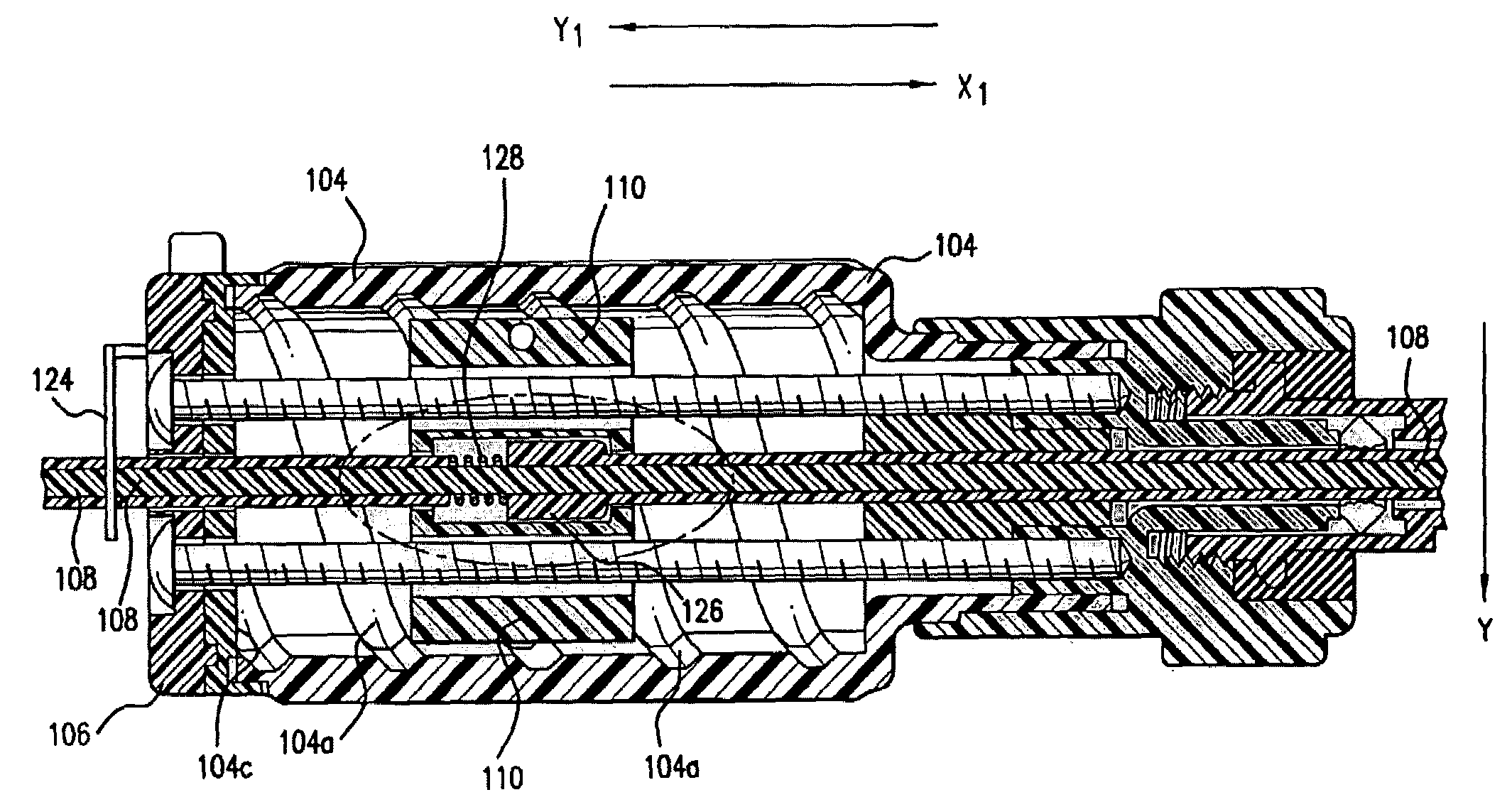
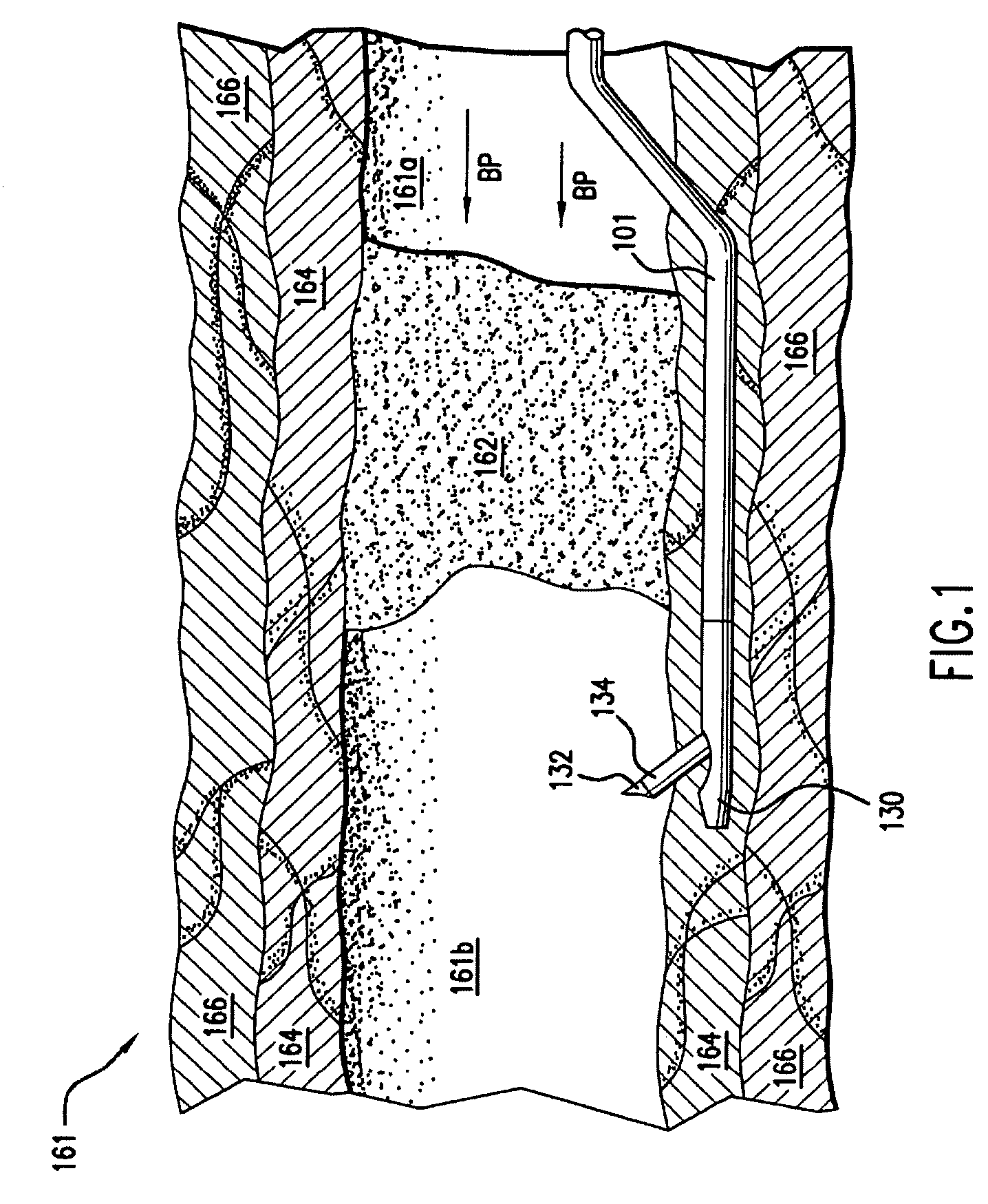
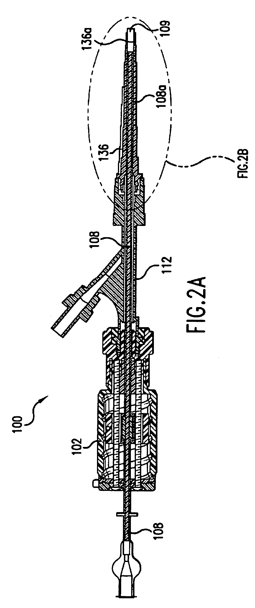
[0038]A device which provides precise movement of a guide tip within a lumen is disclosed. As an overview, the present invention discloses a device which controls a guide tip through a lumen, such as a blood vessel or an artery, of a patient. The device controls the guide tip while a user, such as a surgeon, crosses an occlusion within an artery of a patient in order to allow blood flow through the artery. The device includes a housing having a guide and bushing disposed within the housing. The configuration of the bushing allows for travel of the bushing along the guide within the housing. In accordance with one embodiment of the present invention, the guide within the housing includes grooves and the configuration of the bushing also includes threads complementary to the grooves in the housing such that the threads in the housing guide the bushing. During use of the device, a user rotates a knob which moves the bushing along the grooves within the housing. As will be discussed in ...


PUM

PropertyMeasurementUnit
lengthaaaaaaaaaa
lengthaaaaaaaaaa
lengthaaaaaaaaaa

Abstract

An apparatus for deploying a needle within a lumen is provided. The apparatus includes a housing having a threaded bushing radially disposed therein. The bushing rigidly couples with a nose cone having a guide tip disposed at an end opposite the bushing for penetrating an arterial wall of a lumen. During operation, a user incrementally advances the bushing within the housing, thereby incrementally advancing the guide tip into the lumen. The nose cone also includes a flex guide having a slot configuration which couples with the guide tip which deploys into the lumen along with the guide tip.

Description

BACKGROUND OF THE INVENTION[0001]1. Field of the Invention[0002]The present invention relates generally to catheters and more particularly to a device which provides controlled delivery of a guide tip of a catheter within a lumen having chronic total occlusion.[0003]2. Description of the Related Art[0004]Cardiovascular disease is a leading cause of mortality worldwide. Often times, cardiovascular disease occurs upon chronic total occlusion (CTO) of an artery of a patient. CTO typically occurs after a patient develops atherosclerosis. Blockage of an artery may occur in coronary, peripheral or other arteries. As the blockage continues over time, the blockage become chronic, thereby leading to CTO.[0005]In order to minimize the potential effects of CTO, passage of blood must be restored to the artery. In the past, attempts to restore blood flow included passing a guidewire through the occlusion, thereby forming a passage through which blood may flow. Nonetheless, while attempting to pe...

Claims


Application Information

Patent Timeline
Patent Type & Authority Patents(United States)
IPC IPC(8): A61B5/00A61M25/00A61B17/00A61B17/22A61B19/00
CPCA61B17/3207A61M25/09A61M25/0068A61M25/008A61M25/0084A61M25/0136A61M25/09041A61B17/3478A61B19/54A61B2017/00247A61B2017/00252A61B2017/22042A61B2017/22048A61B2017/22069A61B2017/22077A61B2017/22094A61B2017/22095A61B2017/3409A61B2018/00392A61M25/0069A61M2025/0046A61M2025/0086A61M2025/0087A61M2025/009A61M2025/0096A61M2025/0197A61M2025/09116A61B90/39
Inventor JEN, JIMMYGEORGE, ROBERTDOLIN, JEFFLASSER, AMELIA
Owner ABBOTT LAB INC
Why Eureka
Try Eureka