Firearm modification assembly

a technology of actuating rods and assembly parts, applied in the field of firearms, can solve the problem of taking valuable time to carry out functions,

Active Publication Date: 2007-06-19
GAUNY JUSTIN A +1
View PDF20 Cites 135 Cited by
  • Summary
  • Abstract
  • Description
  • Claims
  • Application Information

AI Technical Summary

Benefits of technology

[0013]It is an aspect of the invention to provide improved elements and arrangements thereof for the pu...

Problems solved by technology

This is undesirable since the “pistol grip” of the carbine or rifle makes an optimum control point on the weapon.
As presently configured, it is effectively necessary t...

Method used


Image

  • Firearm modification assembly
  • Firearm modification assembly
  • Firearm modification assembly

Examples


Embodiment Construction

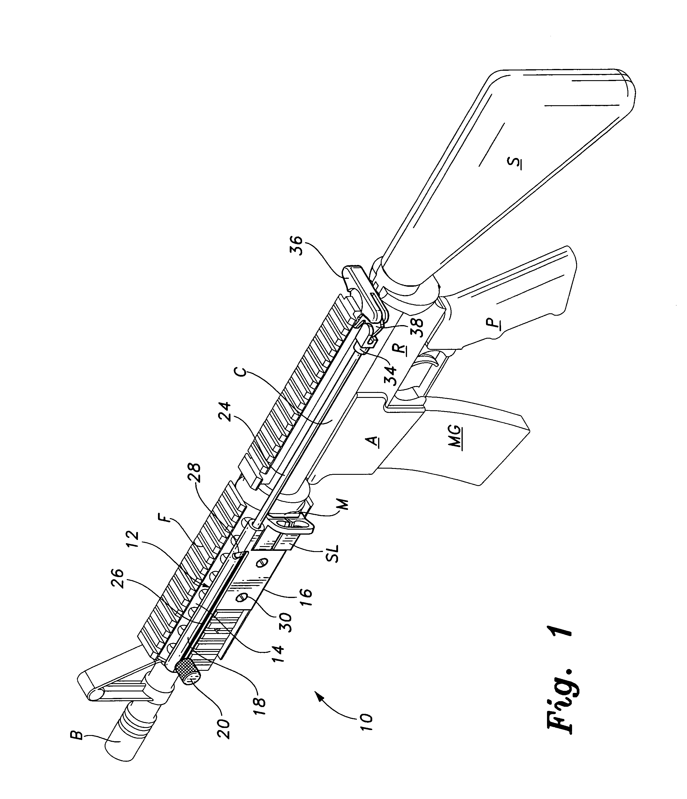
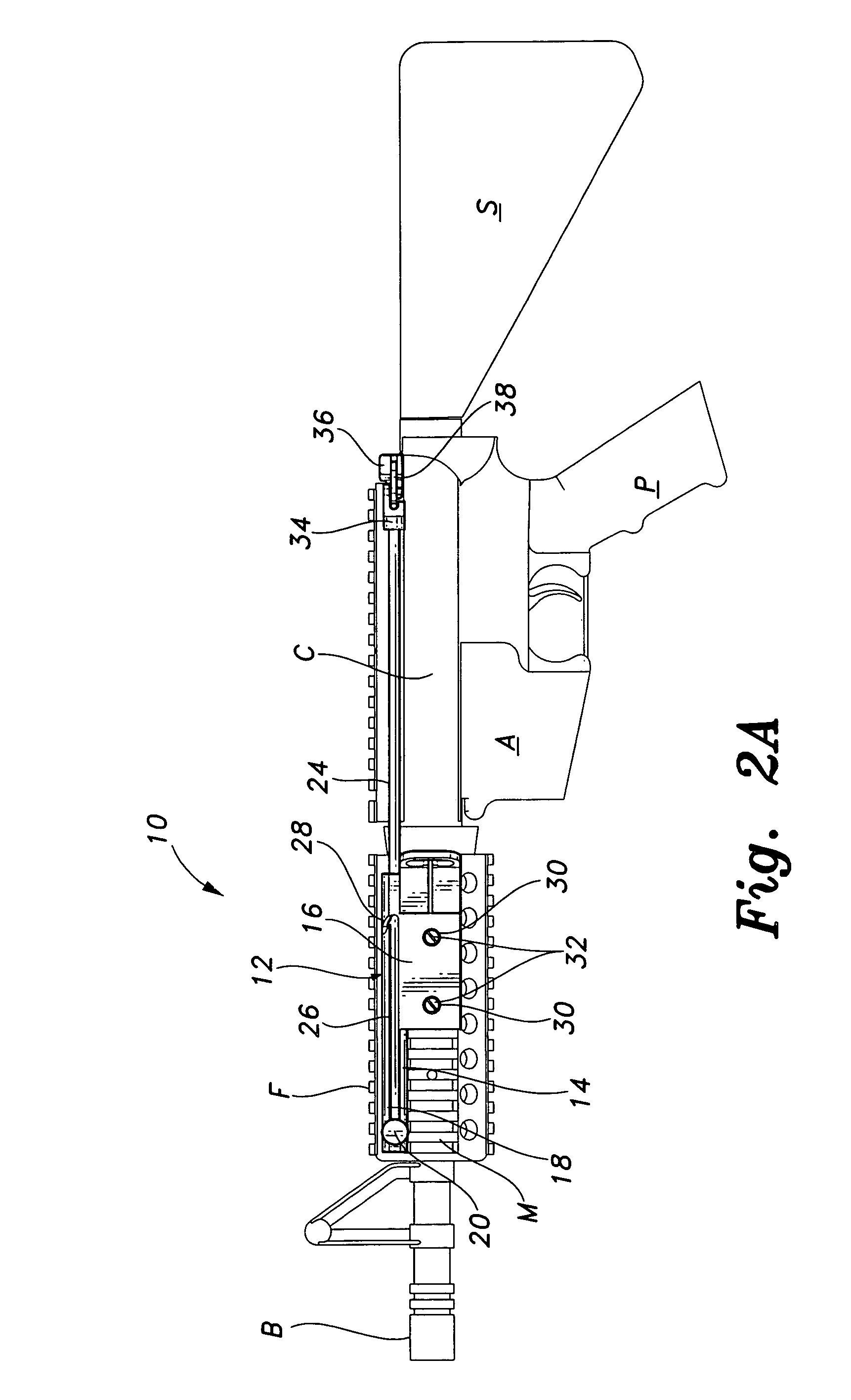
[0026]The present invention is an assembly for modifying a gas-operated automatic firearm such as a carbine or rifle so as to relocate operation of the charging handle of the firearm, such as a Colt M4A1 5.56 carbine or “special purpose” rifles based thereon such as the U.S. SOCOM rifle having both front and rear pistol grips.

[0027]Referring to FIGS. 1 and 2A, there is shown a Colt M4A1 5.56 carbine rifle R having a stock S, a pistol grip P, an ammunition magazine receiver A having a magazine MG, a firing chamber C and a barrel B, foregrip F having a “Weaver” mounting rail M. Carbine charging handle operating system 10 includes a charging handle rod operation assembly 12 mounted between the foregrip F and the charging handle of carbine rifle R. Rod operation assembly 12 includes a foregrip bracket 14 having a rectangular foregrip bracket mount supporting bracket sleeve 18 located on mounting rail M. Also shown on rail M is a commercially available sling SL for mounting a carrying st...


PUM


Abstract

An assembly for modifying an automatic firearm such as a carbine rifle to relocate operation of the firearm charge handle. The assembly includes a fore-grip bracket, a drive rod movable in the foregrip bracket and attached to the charging handle release lever, and a cocking handle attached to the drive rod, the rod being attached to the charge handle for alternately releasing and latching the charge handle for clearing the firearm. In one embodiment, the foregrip bracket is attached to a removable rail attached to the foregrip by a jaw type device. Another embodiment attaches to the foregrip by attaching the foregrip bracket by screws. Another embodiment attaches to a foregrip having no rail by means of a groove cut in the grip, having a pair of spaced apertures into which hooks of foregrip mount, the bracket being held in place by a rod receiver and rotatable latch.

Description

BACKGROUND OF THE INVENTION[0001]1. Field of the Invention[0002]The present invention relates to firearms. More particularly, the present invention relates to an actuating rod assembly addition for operation of the charging handle of an automatic rifle or carbine rifle.[0003]2. Description of the Related Art[0004]A number of functions must be carried out by the user of an automatic firearm such as the Colt M4A1 5.56 carbine or the like. Among these functions include loading, unloading, clearing malfunction, doing “press checks” and locking the bolt. In order to carry out these operations, it is necessary to release the charging handle. As presently configured, the charging handle is gripped behind the trigger location, making it necessary to remove the firing hand from its grip position on the weapon to use that hand to release the charging handle while effectively maintain control of the rifle. This is undesirable since the “pistol grip” of the carbine or rifle makes an optimum con...

Claims


Application Information

Patent Timeline
IPC IPC(8): B64D1/04
CPCF41A3/72
Inventor GAUNY, JUSTIN A.O'NEILL, MICHAEL
Owner GAUNY JUSTIN A
Why Eureka
Try Eureka