Supercharge Your Innovation With Domain-Expert AI Agents!

Modified injection takeout tube

a technology of injection takeout tube and takeout tube, which is applied in the field of cooling device, can solve the problems of increasing reducing the molding injection cycle time, and not being effective in cooling reverse taper style preforms

Inactive Publication Date: 2007-06-19
GRAHAM PACKAGING CO LP
View PDF8 Cites 4 Cited by
  • Summary
  • Abstract
  • Description
  • Claims
  • Application Information

AI Technical Summary

Problems solved by technology

However, conventional take out tubes are not effective in cooling reverse taper style preforms because they fail to make intimate contact with the entire length of the preform.
This failure to cool the entire length of the preform causes an increase in the molding injection cycle time because more time is required to cool those portions of the preform that do not make intimate contact with the inside walls of the take out tube.
However, these attempts have not resulted in a substantial reduction of the molding injection cycle time.
The problem with this approach is that the apparatus only cools the portion of the preform that makes direct contact with the cooled walls of the mold.
Furthermore, this approach does not disclose cooling the preform outside the mold, which results in an increased injection molding cycle time.
The principle problem with the apparatus and method shown in these patents is that the preform is retained in the mold core and this retention significantly increases injection molding cycle time.

Method used


Image

  • Modified injection takeout tube
  • Modified injection takeout tube
  • Modified injection takeout tube

Examples


Embodiment Construction

[0019]A preferred embodiment of the invention is discussed in detail below. While specific exemplary embodiments are discussed, it should be understood that this is done for illustration purposes only. A person skilled in the relevant art will recognize that other components and configurations can be used without parting from the spirit and scope of the invention.

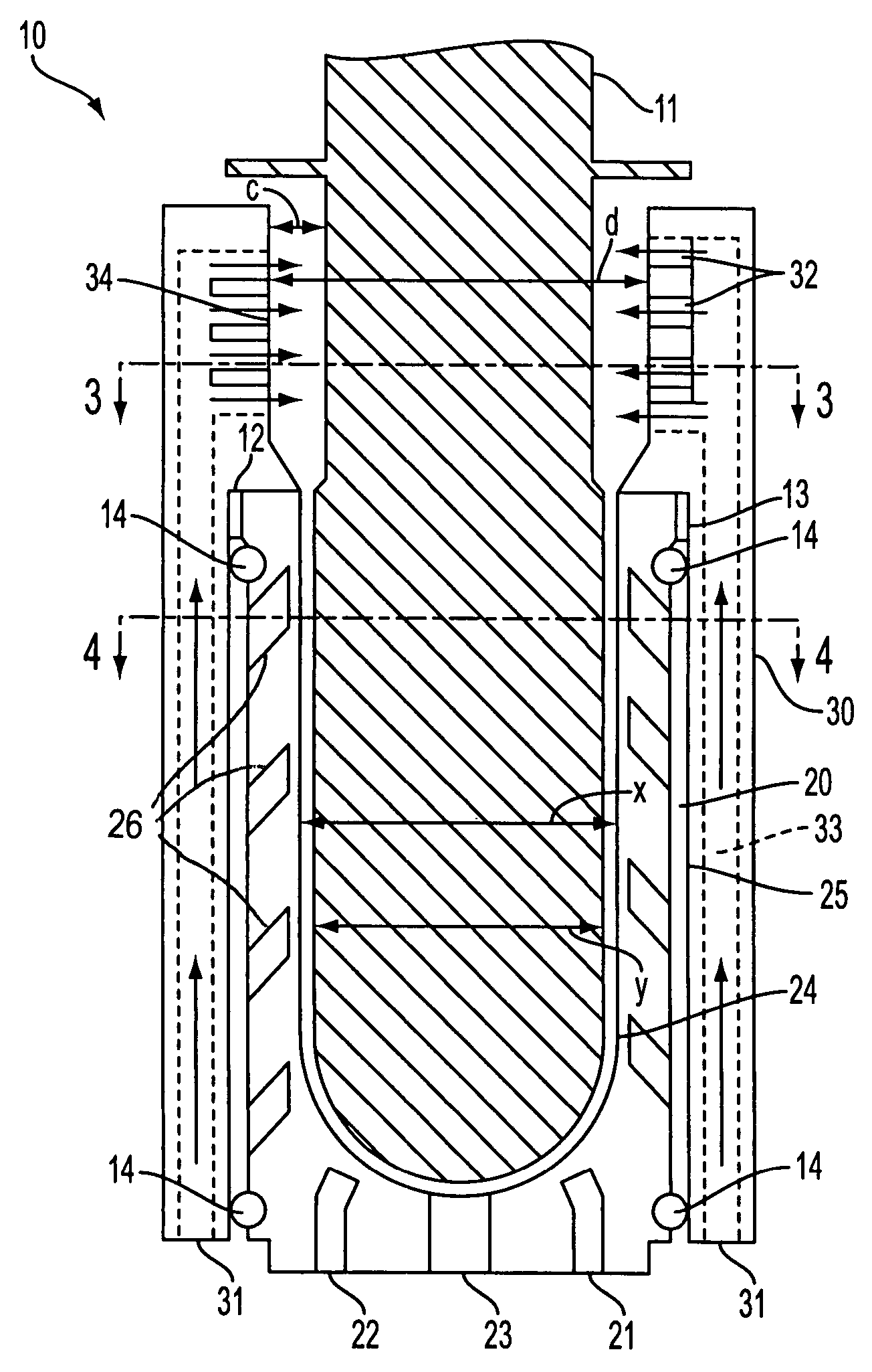
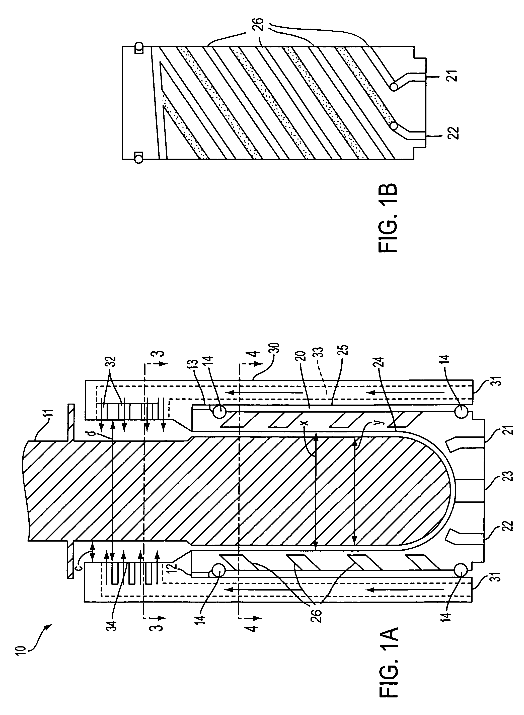
[0020]FIGS. 1A and 1B show a vertical cross-sectional view of a cooling apparatus 10 for use with an injection-molding machine (not shown). The injection-molding machine can include a 20–180 PSI air system (not shown) for use in conjunction with the present invention. Cooling apparatus 10 can include take out tube 20 and cooling sleeve 30, which can be used to cool reverse taper style preform 11 or the like. For a more detailed description of a reverse taper style preform, please refer to the discussion of FIG. 6 below.

[0021]Take out tube 20 can include fluid inlet 21, fluid outlet 22, air passage 23, inner surface 24, and ...


PUM

PropertyMeasurementUnit
areaaaaaaaaaaa
frictionaaaaaaaaaa
diameteraaaaaaaaaa

Abstract

A cooling device and method useful for reducing the total injection molding cycle time of an injection molded tube, and more particularly to applying cooling to areas of a preform that are not in direct contact with the water cooled inside surface of a take out tube.

Description

BACKGROUND OF THE INVENTION[0001]1. Field of the Invention[0002]The present invention relates generally to a cooling device useful for reducing the total injection molding cycle time of an injection molded tube, and more particularly to applying cooling to areas of a preform that are not in direct contact with the water cooled inside surface of a take out tube.[0003]2. Statement of the Prior Art[0004]The manufacture of hot-fill polyethylene terephthalate (PET) containers employs an initial step of forming a parison or preform by an injection molding process. Performs are generally in the shape of a hollow cylinder closed at one end and tapering to form an open end, known as a finish, that can have a diameter that is narrower than the diameter of the closed end. Performs having an open end that is narrower than a closed end are known as reverse taper style performs. To form a reverse taper perform, molten plastic is injected into a mold formed by a cavity and a core and partially coo...

Claims


Application Information

Patent Timeline
Patent Type & Authority Patents(United States)
IPC IPC(8): B29C45/72B29C49/64B29C45/42B29C49/06
CPCB29C45/7207B29C45/4225B29C49/06B29C49/6427B29C2045/7214B29C2045/7264B29C2791/006B29C2791/007B29K2105/253B29C2949/0715B29C49/6435
Inventor DUNMAN, JAMES
Owner GRAHAM PACKAGING CO LP
Features
  • R&D
  • Intellectual Property
  • Life Sciences
  • Materials
  • Tech Scout
  • Unparalleled Data Quality
  • Higher Quality Content
  • 60% Fewer Hallucinations
Learn More