
Methods for centering disks in a magnetic disk assembly

Inactive Publication Date: 2007-06-26
MAXTOR
View PDF4 Cites 4 Cited by
  • Summary
  • Abstract
  • Description
  • Claims
  • Application Information

AI Technical Summary

Benefits of technology

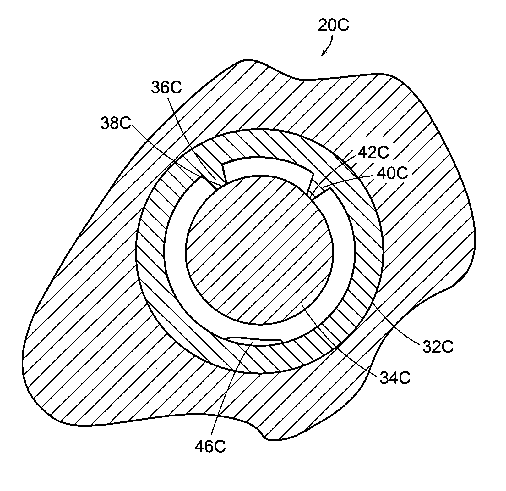
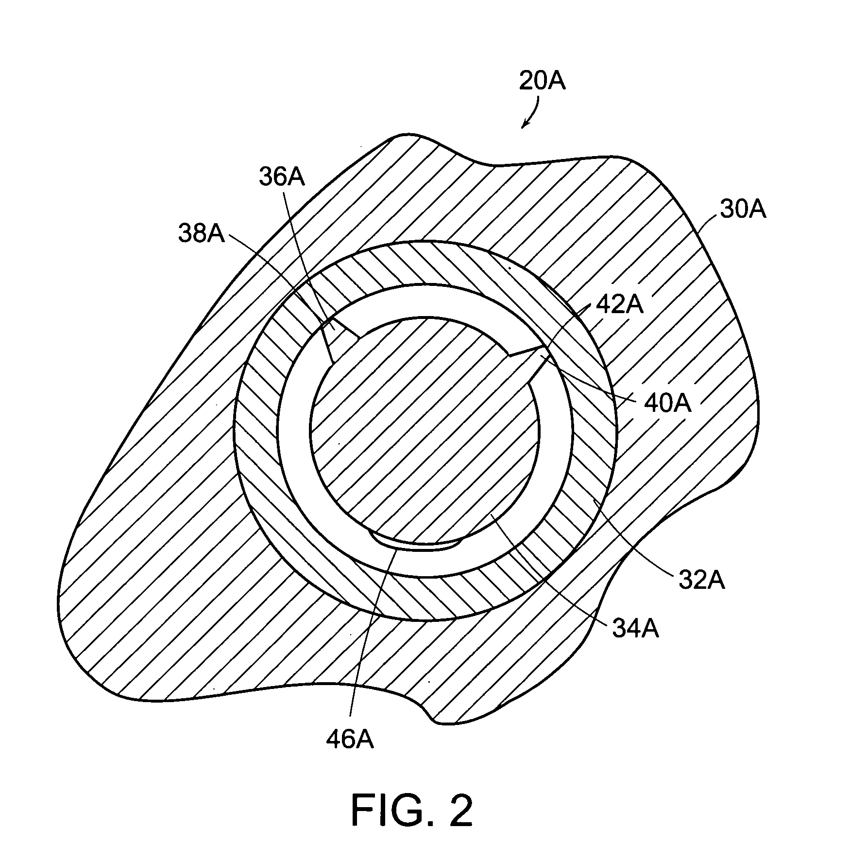
[0010]The present invention is directed to an apparatus or method (or any one or more subparts thereof) for centering a plurality of disks in a disk stack of a magnetic disk drive. In accordance with one aspect of the invention, an apparatus is provided for building a disk stack for inclusion in a magnetic disk drive. A spindle is provided which comprises first and second disk contacts. A mechanism is provided to bias an inner diameter of a stack of plural disks toward both the first disk contact and the second disk contact.
[0011]In accordance with another aspect of the invention, an apparatus or method is provided for building a disk stack for inclusion in a magnetic disk drive. The invention may be directed to any one or more subparts of such an apparatus or method, or to a resulting magnetic disk drive. A s

Problems solved by technology

An out-of-balance condition in the rotating disk stack assembly can cause erratic speed variations in the movement of the disks in relation to the read / write heads, which may produce read / write errors.
Vibrations of the rotating disks can also contribute to head crashes, harming both the disk and read / write head.

Method used


Image

  • Methods for centering disks in a magnetic disk assembly
  • Methods for centering disks in a magnetic disk assembly
  • Methods for centering disks in a magnetic disk assembly

Examples


Embodiment Construction

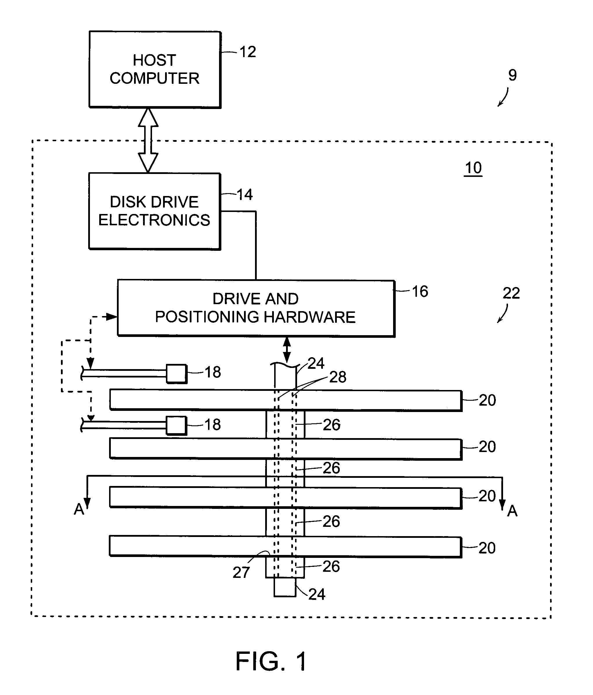
[0017]Referring now to the drawings in greater detail, FIG. 1 shows a schematic diagram of a computer system 9. The illustrated computer system 9 comprises a host computer 12, coupled to a magnetic disk drive 10. Host computer 12 may comprise an individual computer such as a personal computer or a server, or it may comprise a network of computers. Magnetic disk drive 10, having a housing depicted schematically by a square-shaped dotted line, may be installed within a given computer, for example, by plugging magnetic disk drive 10 into a SCSI adapter provided within host computer 12.

[0018]Magnetic disk drive 10 comprises disk drive electronics 14 coupled to host computer 12 via, for example, an adapter such as a SCSI adapter. Drive and positioning hardware 16 is coupled to disk drive electronics 14. Drive and positioning hardware 16 comprises, among other elements not specifically shown in FIG. 1, a read / write head 18 for each disk media surface of each disk provided in a disk stack....


PUM

PropertyMeasurementUnit
Angleaaaaaaaaaa
Angleaaaaaaaaaa
Angleaaaaaaaaaa

Abstract

An apparatus and a method are provided to facilitate building of a disk stack for inclusion in a magnetic disk drive. A spindle is provided which comprises first and second disk contacts. A mechanism is provided to bias an inner diameter of a stack of plural disks toward both the first disk contact and the second disk contact. The spindle may comprise one or a pair of lateral protrusions. The apex of each such spindle lateral protrusions may comprise one or both of the disk contacts. In addition, or alternatively, the inner diameter of a disk, to be inserted over the spindle, may comprise one or a pair of lateral protrusions. The apexes of such disk lateral protrusions may comprise one or both of the first disk contact and the second disk contact.

Description

COPYRIGHT NOTICE[0001]This patent document contains information subject to copyright protection. The copyright owner has no objection to the facsimile reproduction by anyone of the patent document or the patent, as it appears in the US Patent and Trademark Office files or records, but otherwise reserves all copyright rights whatsoever.BACKGROUND OF THE INVENTION[0002]1. Field of the Invention[0003]The present invention relates to magnetic disk drives, and methods for forming a disk stack assembly with concentrically-aligned disks.[0004]2. Description of Background Information[0005]Magnetic disk drives store data for use by all types of computer systems. A magnetic disk drive typically has a case, enclosing one or more spinning disks (also known as “platters”), arranged one on top of another in a stack. An actuator arm of the hard disk drive responds to commands the drive receives from a host computer, and the actuator arm moves to a proper location on the disk. When the actuator arm...

Claims


Application Information

Patent Timeline
IPC IPC(8): G11B5/127H04R31/00
CPCG11B17/038Y10T29/49025Y10T29/49027
Inventor MALLARY, MICHAEL
Owner MAXTOR
Learn More