Combination valve and regulator with vented seat for use with pressurized gas cylinders, particularly oxygen cylinders

a technology of pressure gas cylinders and regulators, which is applied in fluid pressure control, process and machine control, instruments, etc., can solve the problems of affecting the safety of the user, the seat is often subject to strong frictional interference, and the fire downstream of the cylinder valv

Inactive Publication Date: 2007-06-26
LUXFER INC
View PDF40 Cites 74 Cited by
  • Summary
  • Abstract
  • Description
  • Claims
  • Application Information

AI Technical Summary

Problems solved by technology

Oxygen cylinder valves, as they exist today, have been implicated in numerous fire incidents with sometimes catastrophic results.
When a cylinder valve seat ignites, the attached regulator or manifold system is subjected to strong kindling chain mechanisms that will often lead to fires downstream of the cylinder valve.
Further, due to the rotating seat mechanism, the seat often is subjected to strong frictional interference with the valve nozzle.
Both of these features are undesirable to prudent persons aware of the fire hazards of handling oxygen cylinders.
Conventional known valves are also “dirty,” generating large amounts of undesirable debris due to their mode of operation (i.e., rotating seat and threads in the oxygen wetted portion of the valve).
This debris often deposits in the nonmetallic seat itself and increases the frictional interactions during valve opening and closing.
Both nylon and PPO exhibit poor to moderate compatibility based on present oxygen-compatibility rating test standards, and deliver a large amount of energy if ignited.
PCTFE is considered an oxygen compatible material, but has a compressive modulus that is insufficient to withstand the torques that are often applied by the manual closing of conventional valves.
As a result, PCTFE seated plug-valves often exhibit significant extrusion and recently have been implicated in a large number of fires.
The extruded seat increases the surface-area-to-volume ratio for oxygen gas impingement during discharge, and is believed to greatly increase vulnerability of the seat to hazardous flow friction ignition.
Further, many of the materials in use with known valves seats generate highly toxic gases when they bum.

Method used


Image

  • Combination valve and regulator with vented seat for use with pressurized gas cylinders, particularly oxygen cylinders
  • Combination valve and regulator with vented seat for use with pressurized gas cylinders, particularly oxygen cylinders
  • Combination valve and regulator with vented seat for use with pressurized gas cylinders, particularly oxygen cylinders

Examples


Embodiment Construction

)

[0036]The inventive valve-regulator apparatus ameliorates vulnerability to the common ignition mechanisms that are observed in oxygen systems. The invention satisfies the recommended design criteria that have been established in standards such as ASTM G88, “Design Guide for Oxygen Systems,” ASTM G128, “Control of Hazards and Risks in Oxygen Enriched Systems,” ASTM G63, “Evaluating Nonmetallic Materials for Oxygen Service,” and ASTM G94, “Evaluating Metals for Oxygen Service.” The ignition mechanisms that are specifically eliminated by the design features of the present invention are adiabatic compression, flow friction / flow erosion, particle impact, mechanical impact, frictional heating, and kindling chain / promoted ignition. Before disclosing specifics of the invention, its design advantages are discussed generally.

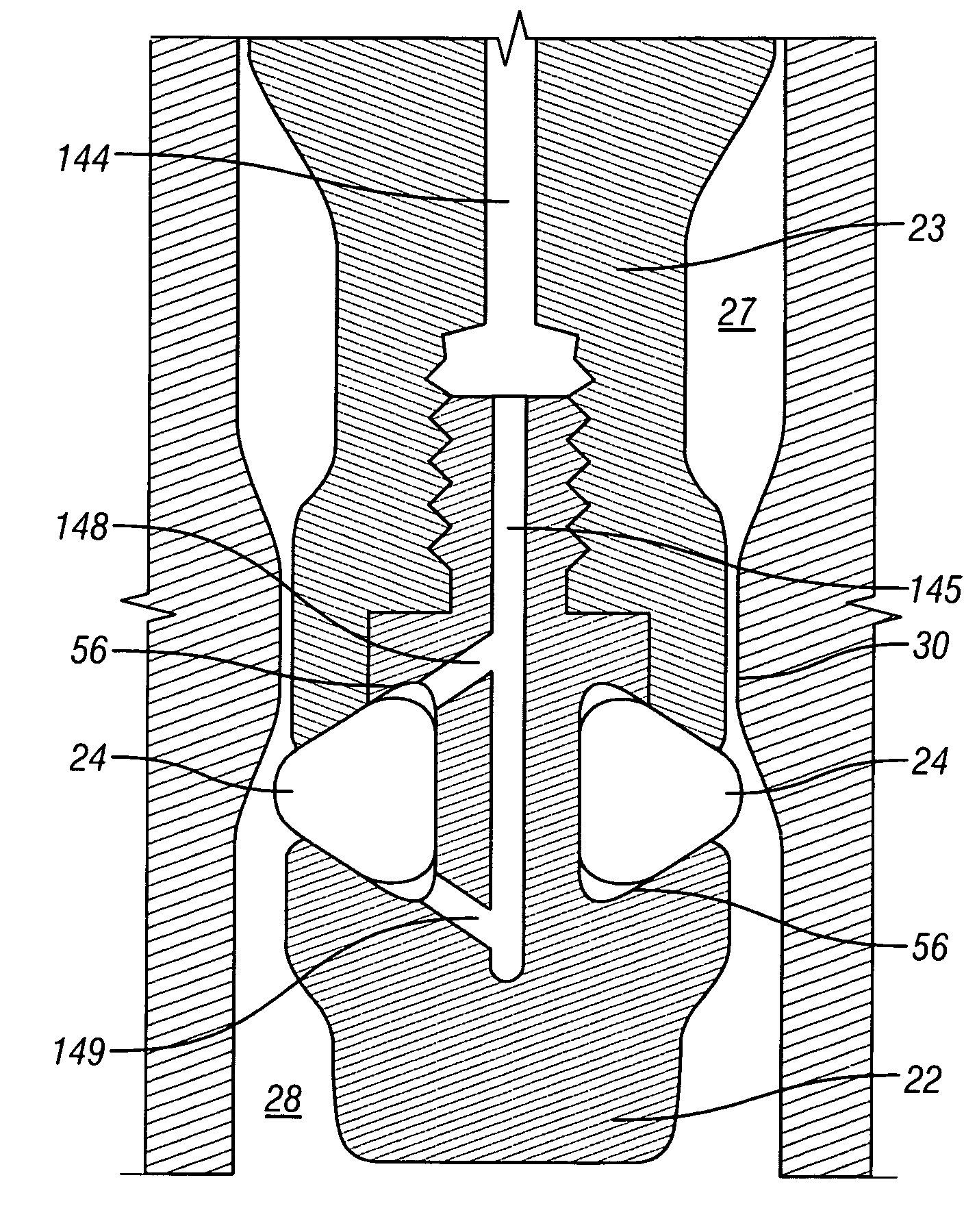
[0037]The design of the apparatus ensures that the main seat is protected from the discharge flow and is not subject to “flow impingement.” This reduces seat ignition me...


PUM


Abstract

A combined valve-regulator apparatus, for safely regulating the flow of combustible gases such as oxygen. A compressible o-ring is used to provide controllable sealed seating of the valve and regulator during operation. A system is provided in the valve-regulator apparatus for venting the o-ring seat elements, to minimize undesirable ballooning or extrusion otherwise resulting from dynamic pressures and changing forces due to rapid gas flows through the regulator.

Description

CROSS-REFERENCE TO RELATED APPLICATIONS[0001]This application is a continuation-in-part application of U.S. patent application Ser. No. 10 / 644,704 entitled “Valve Embodiment and Combination Valve and Regulator for Use with Pressurized Gas Cylinders, Particulalrly Oxygen Cylinders,” filed Aug. 19, 2003, which was a continuation-in-part application of U.S. patent application Ser. No. 09 / 872,233, entitled “Cylinder Valve and Bayonet Check Filter with Excess Flow Protection Feature,” now issued as U.S. Pat. No. 6,607,007, and the specifications thereof are incorporated herein by reference.[0002]This application also claims the benefit of the filing of U.S. Provisional Patent Application Ser. No. 60 / 548,759, entitled “Vented O-ring Seat for Use in Combination Valve and Regulator for Use with Pressurized Gas Cylinders,” filed on Feb. 26, 2004, and also of U.S. Provisional Patent Application Ser. No. 60 / 615,273, entitled “Venting System for Use in Combination Vale and Regulator for Use wit...

Claims


Application Information

Patent Timeline
Patent Type & Authority Patents(United States)
IPC IPC(8): F16K1/46G05D7/00G05D7/01
CPCG05D7/0126Y10S251/90Y10T137/87917
Inventor HULL, WENDELLNEWTON, BARRY E.
Owner LUXFER INC
Why Eureka
Try Eureka