Artificial intervertebral disc

a technology of artificial vertebrae and discs, applied in the field of artificial vertebrae, can solve the problems of unavoidable difference between static and dynamic friction coefficients of spherical joints in state-of-the-art prosthetics, unnatural feelings, and inevitable wear of sliding connections

Inactive Publication Date: 2007-06-26
U S SPINAL TECH +3
View PDF5 Cites 106 Cited by
  • Summary
  • Abstract
  • Description
  • Claims
  • Application Information

AI Technical Summary

Problems solved by technology

Intervertebral disc prosthetics must comply with several requirements, often contradicting each other.
This also results in some unnatural feelings, since the elastic resistance forces in the natural spinal column are not significantly dependent on the axial force.
Another shortcoming of the state-of-the-art prosthetics is an unavoidable difference between static and dynamic friction coefficients in spherical joint.
Yet another shortcoming, which is also a result of frictional interaction in the spherical joint, is inevitable wear of the sliding connection.
The wear process creates worn-out particles which are contaminating the area around the disc and may increase the friction forces if accumulated in the sliding connection.

Method used


Image

  • Artificial intervertebral disc
  • Artificial intervertebral disc
  • Artificial intervertebral disc

Examples


Embodiment Construction

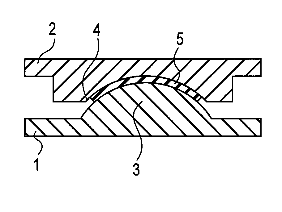
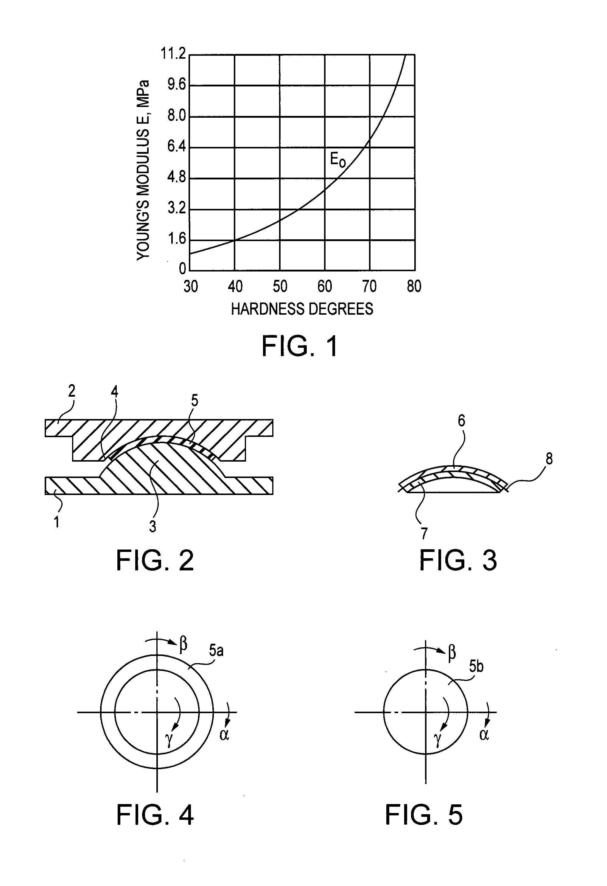
[0023]A “rigid” component in this Specification means a component having significantly lesser deformations than the elastomeric element(s) connecting these components. Specifically, “rigid” is defined here as having the Young's modulus at least ten times greater than the Young's modulus E0 of an elastomer having hardness H60 on scale A of Shore Durometer. This corresponds, in accordance with the industry-accepted correlation shown in FIG. 1, to the Young's modulus E≈3G≧10E0=˜40 MPa, where G is the shear modulus.

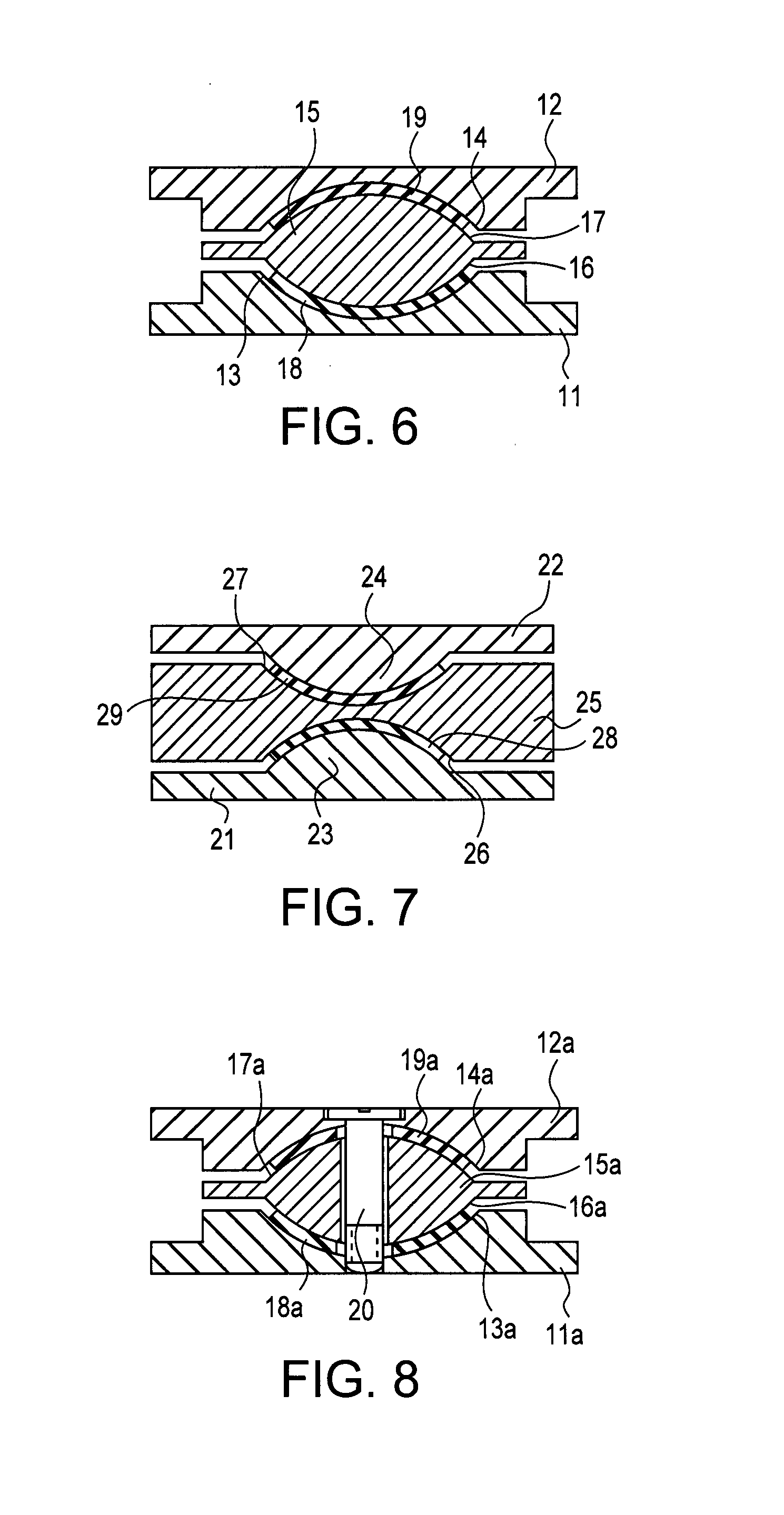
[0024]Four embodiments of the proposed disc design are shown in FIGS. 2, 6, 7, and 8.

[0025]FIG. 2 shows an artificial disc comprising lower base 1 and upper base 2, both made of a metal, plastic, or other rigid material. One of the bases has a convex spherical protrusion 3 (shown on the lower base 1), while another base (top base 2 in FIG. 2) has a concave spherical socket 4 coaxial with protrusion 3. Bases 1 and 2 do not have a direct contact, and the space between protrusio...


PUM


Abstract

The instant invention proposes an artificial intervertebral disc providing for angular displacements between adjacent vertebrae wherein these displacements are accommodated by internal shear in an elastomeric layered element residing between the upper and lower bases attached, respectively, to the upper and lower adjacent vertebrae, without sliding.

Description

[0001]Priority as of Jan. 13, 2004 is requested per Provisional Application 60 / 535,741.FIELD OF THE INVENTION[0002]The invention relates to designs of artificial intervertebral discs for prosthetic and dummy applications.BACKGROUND OF THE INVENTION[0003]Intervertebral disc prosthetics must comply with several requirements, often contradicting each other. These requirements are derived from studies on natural intervertebral discs. The prosthetic artificial disc should provide angular mobilities with specified ranges and stiffness values (two bending mobilities, fore-and-aft and side-to-side, and torsional around the axis of the spine), while accommodating large and varying axial (vertical) loading; it is desirable that the stiffness values are not significantly influenced by the changing vertical loads. Dummies are mock-ups of human bodies designed to simulate behavior of human bodies in extreme circumstances, e.g. crash dummies. Dummies are not, usually, equipped with all individual...

Claims


Application Information

Patent Timeline
Patent Type & Authority Patents(United States)
IPC IPC(8): A61F2/44A61F2/00A61F2/30
CPCA61F2/4425A61F2002/30014A61F2002/30362A61F2002/30434A61F2002/30448A61F2002/30649A61F2002/30685A61F2002/30929A61F2002/30971A61F2220/0033A61F2220/0041A61F2220/005A61F2250/0018A61F2002/30433
Inventor RIVIN, EVGENY I.
Owner U S SPINAL TECH
Why Eureka
Try Eureka