Heating apparatus with mechanical attachment

a technology of mechanical attachment and heater, which is applied in the direction of heater elements, instruments, electrographic processes, etc., can solve the problems of significant investment in processing equipment, structural failure of heater, and relatively long “cycle tim

Active Publication Date: 2007-06-26
LEXMARK INT INC
View PDF8 Cites 72 Cited by
  • Summary
  • Abstract
  • Description
  • Claims
  • Application Information

AI Technical Summary

Problems solved by technology

Assembly of the heater to the supporting member using adhesive generally requires a significant investment in processing equipment, as well as a relatively long “cycle time,” such as twenty-four hours, to allow the adhesive to cure.
The adhesive bond may limit thermal expansion of the heater relative to the supporting member where the heater and supporting member have different coefficients of thermal expansion, and thus may cause a structural failure of the heater due to thermally induced stresses.
Also, it has been observed that many “late” to “end of life” heater assembly failures have occurred as a result of a failure of the bond formed by the adhesive between the heater and the supporting member.
This failure of the adhesive bond may allow the heater to move on the supporting member in an uncontrolled manner in the process direction.
W

Method used


Image

  • Heating apparatus with mechanical attachment
  • Heating apparatus with mechanical attachment
  • Heating apparatus with mechanical attachment

Examples


Embodiment Construction

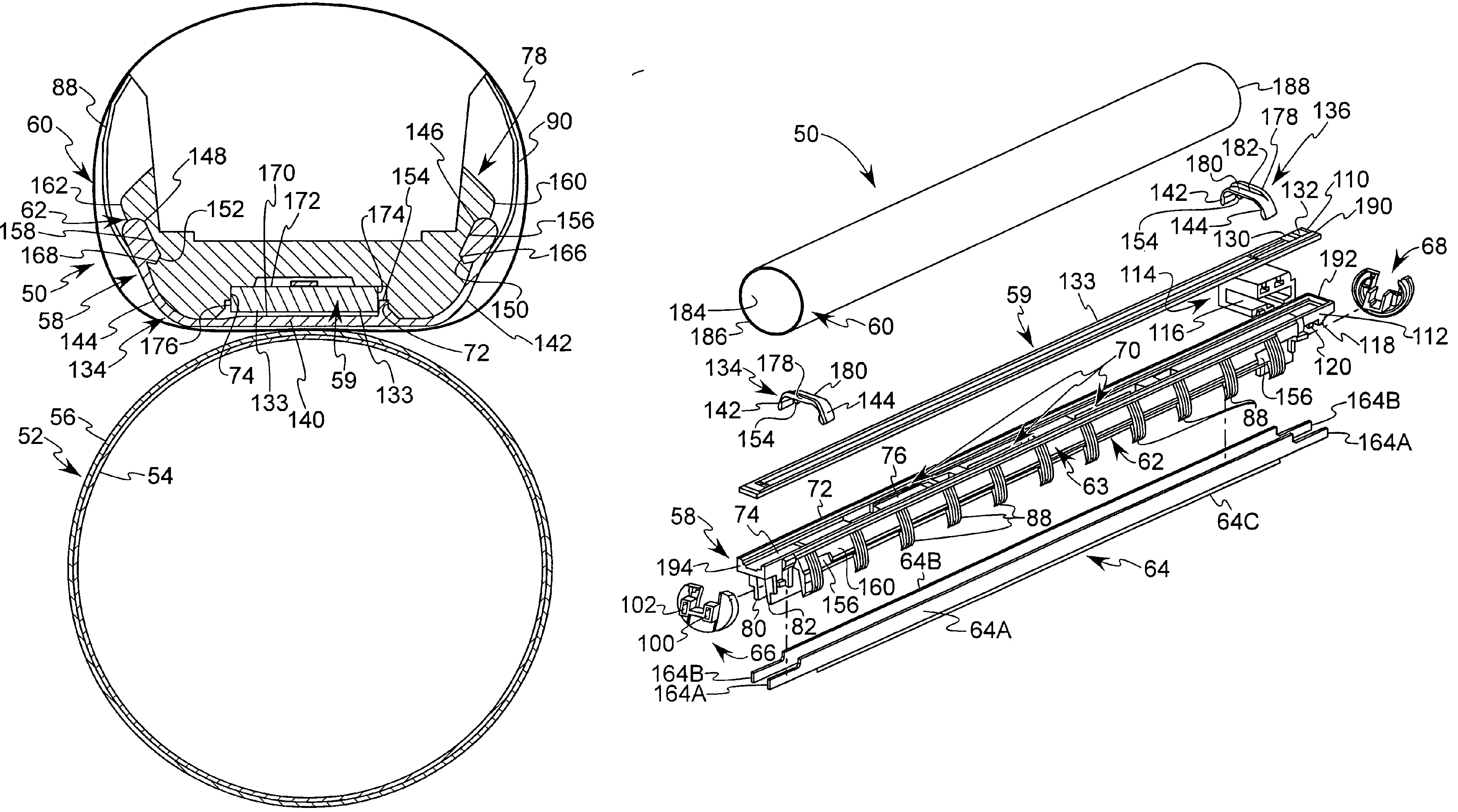
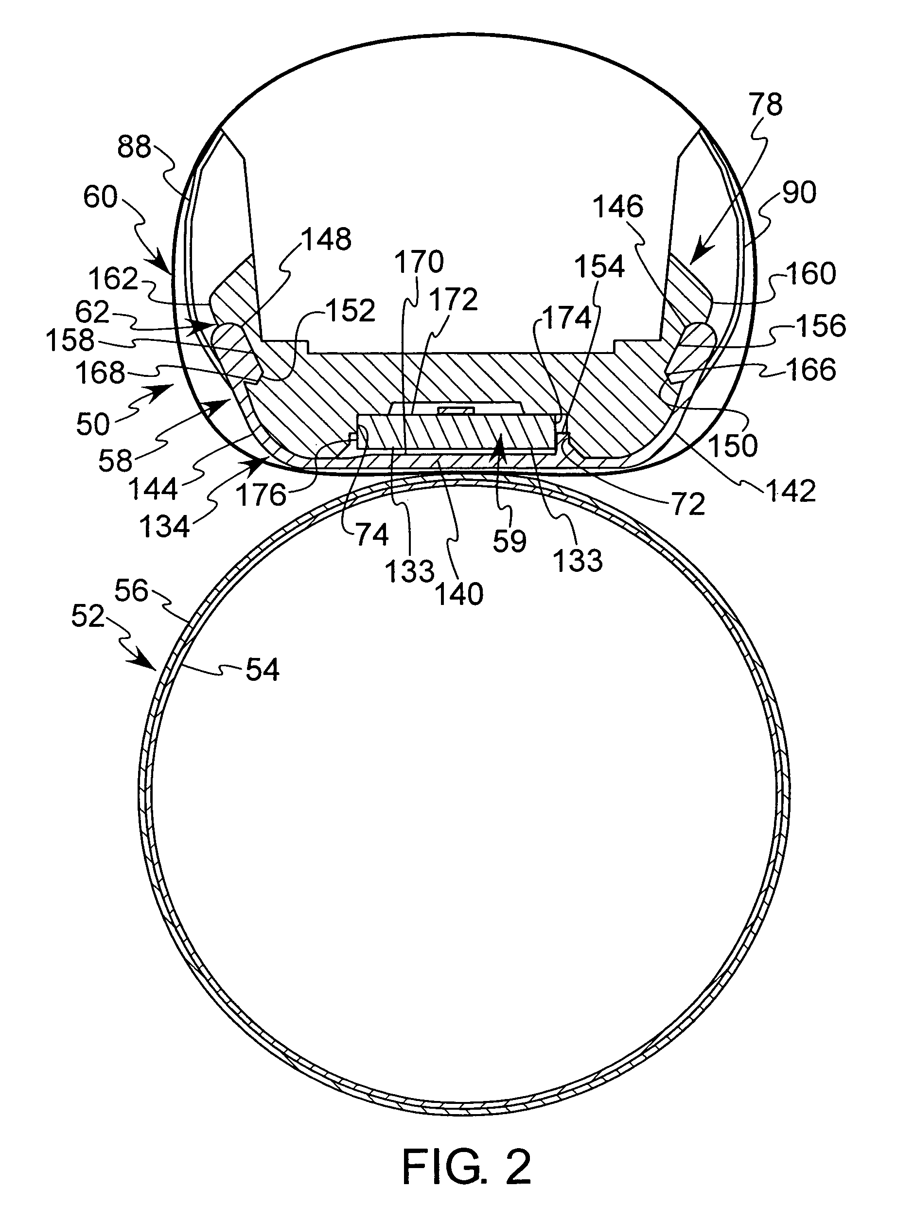
[0020]In the following detailed description of the preferred embodiment, reference is made to the accompanying drawings that form a part hereof, and in which is shown by way of illustration, and not by way of limitation, a specific preferred embodiment in which the invention may be practiced. It is to be understood that other embodiments may be utilized and that changes may be made without departing from the spirit and scope of the present invention.

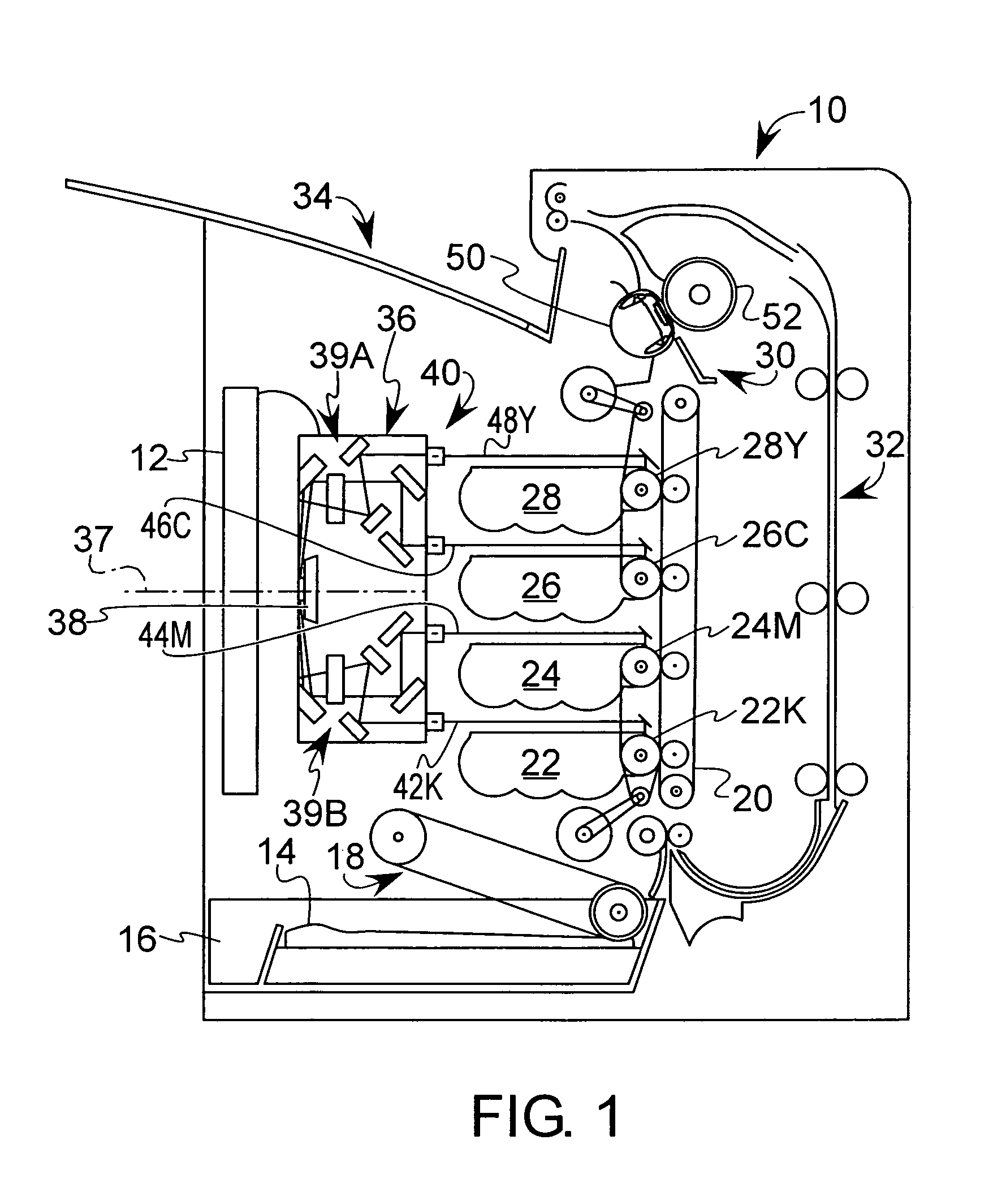
[0021]FIG. 1 depicts a representative electrophotographic image forming apparatus, such as a color laser printer, which is indicated generally by the numeral 10. An image to be printed is electronically transmitted to a print engine controller or processor 12 by an external device (not shown) or may comprise an image stored in a memory of the processor 12. The processor 12 includes system memory, one or more processors, and other logic necessary to control the functions of electrophotographic imaging.

[0022]In performing a printing operat...


PUM


Abstract

In accordance with an aspect of the present invention, an image heating apparatus is provided for fusing an unfixed toner image to a substrate including a housing base for supporting a heater, and a thin film or belt extending around the housing base and heater. The heater is held to the housing base by a fastener structure that may include a pair of retainer clips having opposing ends attached to the housing base and having a central portion extending across the heater for retaining the heater in position. The clips may include outwardly extending walls for engaging edges of the belt to maintain the lateral position of the belt.

Description

BACKGROUND OF THE INVENTION[0001]1. Field of the Invention[0002]The present invention relates to an electrophotographic image forming apparatus, and more particularly to a heater attachment structure for use in a fusing system of such an apparatus.[0003]2. Description of Related Art[0004]In an electrophotographic image forming apparatus, such as a printer or copier, a latent image is formed on a light sensitive drum and developed with toner. The toner image is then transferred onto media, such as a sheet of paper, and is subsequently passed through a fuser assembly where heat and pressure are applied to melt and adhere the unfused toner to the surface of the media. There are a variety of devices to apply heat and pressure to the media such as radiant fusing, convection fusing, and contact fusing. Contact fusing is the typical approach of choice for a variety of reasons including cost, speed and reliability. Contact fusing systems themselves can be implemented in a variety of manners...

Claims


Application Information

Patent Timeline
IPC IPC(8): G03G15/20
CPCG03G15/2064G03G21/1685G03G2215/2016G03G2215/2035
Inventor MAUL, MICHAEL D.GILMORE, JAMES D.CRETEAU, GREGORY D.
Owner LEXMARK INT INC
Why Eureka
Try Eureka