Single-use medical device
- Summary
- Abstract
- Description
- Claims
- Application Information
AI Technical Summary
Benefits of technology
Problems solved by technology
Method used
Image

Examples
first embodiment
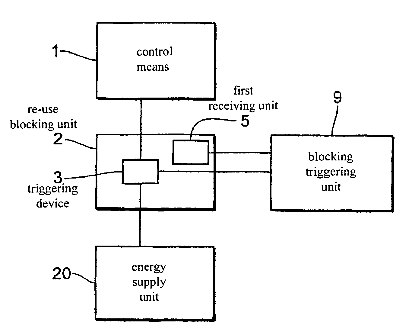
[0050]FIG. 1 shows a block circuit diagram of an electrical therapy device in accordance with a The electrical therapy device has a control means 1, a blocking triggering unit 9, a re-use blocking unit 2 and an energy supply unit 20. The re-use blocking unit 2 is respectively connected to the control means 1, the blocking triggering unit 9 and the energy supply unit 20. The re-use blocking unit 2 has a triggering device 3 and a first receiving unit 5. The triggering device 3 is connected to the control means 1, the energy supply unit 20 and the blocking triggering unit 9. The first receiving unit 5 is connected to the blocking triggering unit 9.
[0051]The first receiving unit 5 is a wirelessly activatable receiving unit such as for example a telemetric receiving unit or a magnetically activatable receiving unit. The first receiving unit 5 can be activated for example by a telemetric signal (in the case of a telemetric receiving unit) or by a magnet (in the case of a magnetically act...
second embodiment
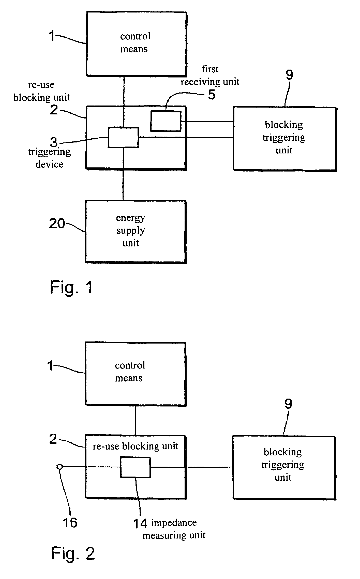
[0054]FIG. 2 shows a block circuit diagram of an electrical therapy device in accordance with the In this arrangement the therapy device has a control means 1, a re-use blocking unit 2 and a blocking triggering unit 9. The electrical therapy device also has a connection 16 for an electrode line. The re-use blocking unit 2 is respectively connected to the control means 1, the blocking triggering unit 9 and the connection 16 and has an impedance measuring unit 14. In this case the impedance measuring unit 14 is connected to the connection 16 for the electrode line and to the blocking triggering unit 9.
[0055]The impedance measuring unit 14 detects the impedance at the connection 16 and thus the impedance of a connected electrode line. That detection operation can be effected continuously or at discrete intervals of time. In the impedance measuring unit 14, the measured impedance values are compared to a previously inputted threshold value or range of threshold values. If the measured ...
third embodiment
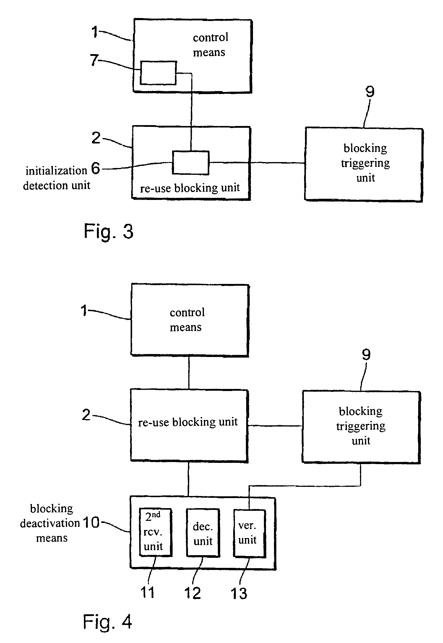
[0058]FIG. 3 shows a block circuit diagram of an electrical therapy device in accordance with a The electrical therapy device in this case has a control means 1, a re-use blocking unit 2 and a blocking triggering unit 9. The re-use blocking unit 2 in this arrangement is respectively connected to the control means 1 and the blocking triggering unit 9. The control means 1 has a memory 7 for the storage of a works operating program. The re-use blocking unit 2 has an initialisation detection unit 6 connected to the blocking triggering unit 9 and the memory 7.
[0059]The initialisation detection unit 6 detects initialisation of the works operating program in the memory 7 for control of the electrical therapy device in accordance with the patient-specific parameters during implantation of the electrical therapy device in a body. When such initialisation of the works operating program has been detected the initialisation detection unit 6 activates the blocking triggering unit 9.
[0060]Upon e...
PUM
 Abstract
Description
Claims
Application Information
 - R&D Engineer
- R&D Manager
- IP Professional
- Industry Leading Data Capabilities
- Powerful AI technology
- Patent DNA Extraction
Browse by: Latest US Patents, China's latest patents, Technical Efficacy Thesaurus, Application Domain, Technology Topic.
© 2024 PatSnap. All rights reserved.Legal|Privacy policy|Modern Slavery Act Transparency Statement|Sitemap