Zero-turn radius vehicle with steerable front wheels

a technology of steering wheel and zero-turn radius, which is applied in the direction of non-deflectable wheel steering, transportation and packaging, agriculture tools and machines, etc., can solve the problems of asynchronous steering system and inability to driv

Inactive Publication Date: 2007-07-03
GIZMOW
View PDF15 Cites 98 Cited by
  • Summary
  • Abstract
  • Description
  • Claims
  • Application Information

AI Technical Summary

Benefits of technology

The technical effect of this patent is to provide a mechanism for controlling the speed of wheels on vehicles through steering inputs from drivers. By designing cams and cam followers that produce a compressive force or“push” on the inner drive wheel at different points during turns, the vehicle can be controlled to respond accordingly.

Problems solved by technology

The technical problem addressed in this patent text needs to be identified by a senior R&D personnel who has read it through.

Method used


Image

  • Zero-turn radius vehicle with steerable front wheels
  • Zero-turn radius vehicle with steerable front wheels
  • Zero-turn radius vehicle with steerable front wheels

Examples


Embodiment Construction

[0077]While the present invention will be described more fully hereinafter with reference to the accompanying drawings in which particular embodiments and methods are shown, it is to be understood from the outset that persons of ordinary skill in the art may modify the invention herein described while achieving the functions and results of this invention. Sound engineering judgment may be used to modify various aspects and components of the invention without detracting from the broad, general teachings hereof. Accordingly, the description that follows is to be understood as illustrative and exemplary of specific embodiments within the broad scope of the present invention and not as limiting the scope of the invention. In the following descriptions, like numbers refer to similar features or like elements throughout.

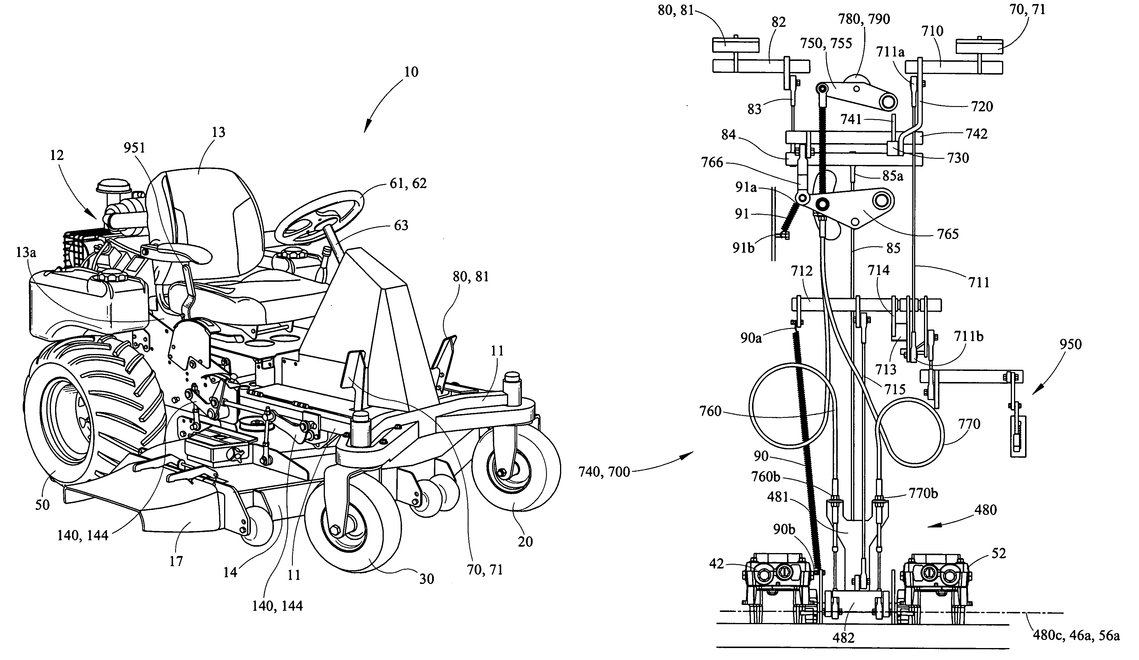
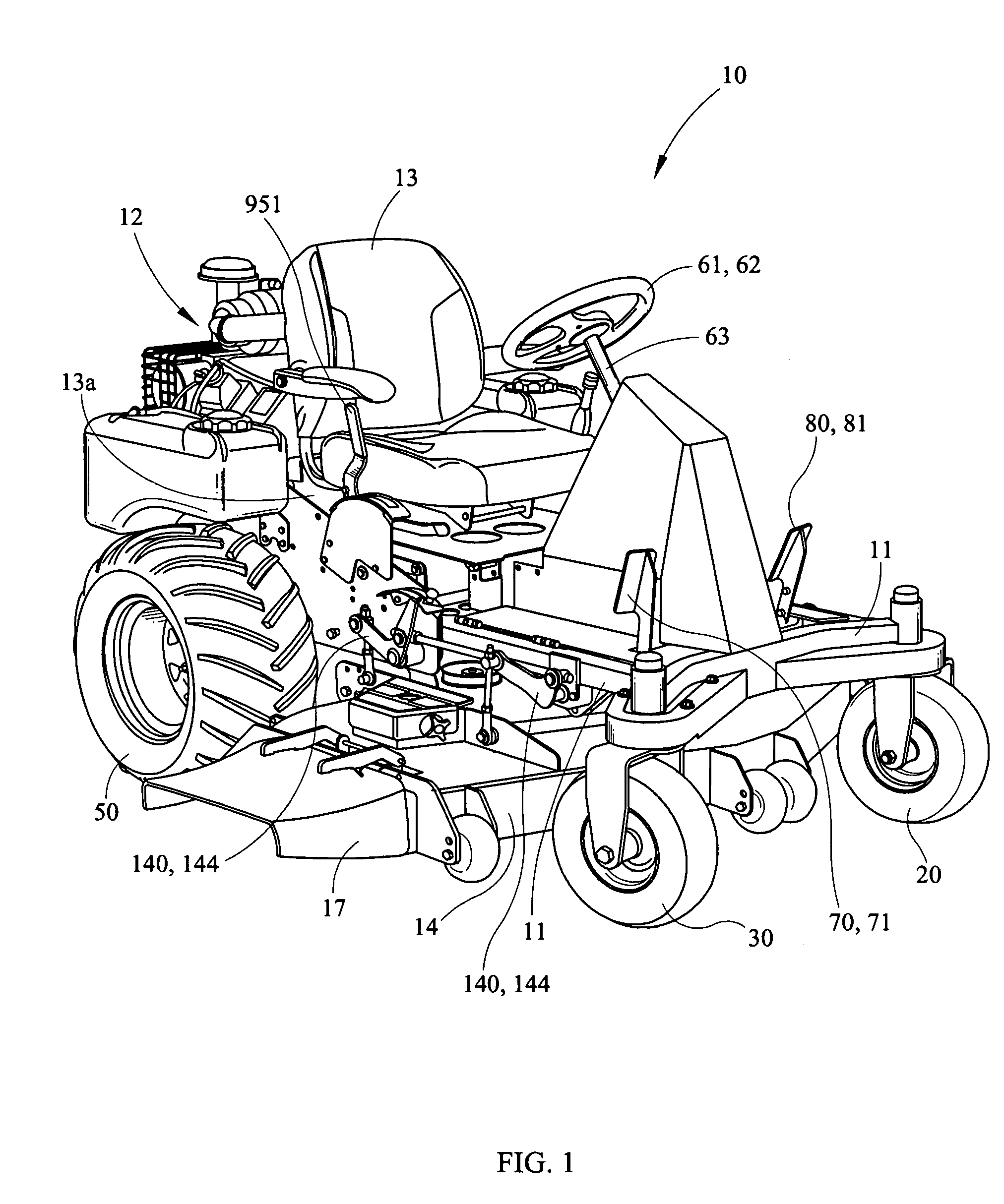
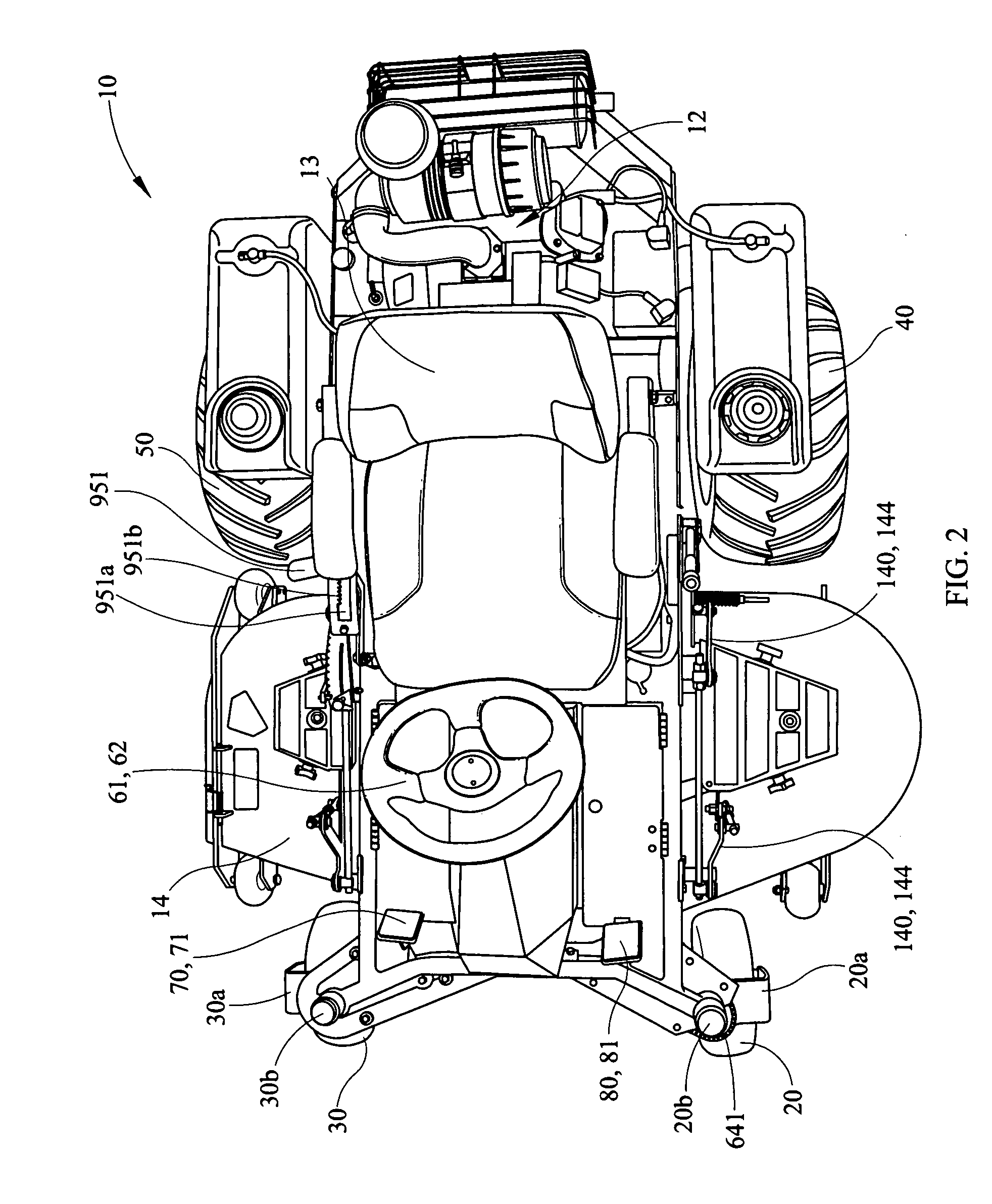
[0078]FIGS. 1 through 37 depict an apparatus 10 in the form of a vehicle according to one embodiment of the invention. Throughout this description the terms “apparatus” an...


PUM


Abstract

The present invention relates to a zero turning radius vehicle having at least one steerable front wheel and a multistage steering input system separately capable of steering the at least one front wheel and selectively driving the drive wheels. A front wheel steering system comprises at least one oblongated sprocket meshingly connected to a steering shaft. An engagement cam system provides the ability to selectively, independently couple the steering wheel to pump arms driving a first and second drive wheel. A steering cam shaft comprises at least one steering cam that acts on at least one bearing. Once the engagement cam system rotates the at least one bearing into place to receive the at least one steering cam, rotation of the steering cam independently alters the speed of one drive wheel in relation to the other drive wheel in response to steering input provided by the operator.

Description


Claims


Application Information

Patent Timeline
Owner GIZMOW
Why Eureka
Try Eureka