Audio jack connector

Inactive Publication Date: 2007-07-03
CHENG UEI PRECISION IND CO LTD
View PDF26 Cites 27 Cited by
  • Summary
  • Abstract
  • Description
  • Claims
  • Application Information

AI Technical Summary

Benefits of technology

[0008]It is therefore an object of the present invention to provide an audio jack connector c

Problems solved by technology

However, the contacts of the conventional audio jack connector as described above soldered to the external printed circuit board are easy to be loosen, and such disengagement may affect audio signals transmission.
However, the aud

Method used


Image

  • Audio jack connector
  • Audio jack connector
  • Audio jack connector

Examples


Embodiment Construction

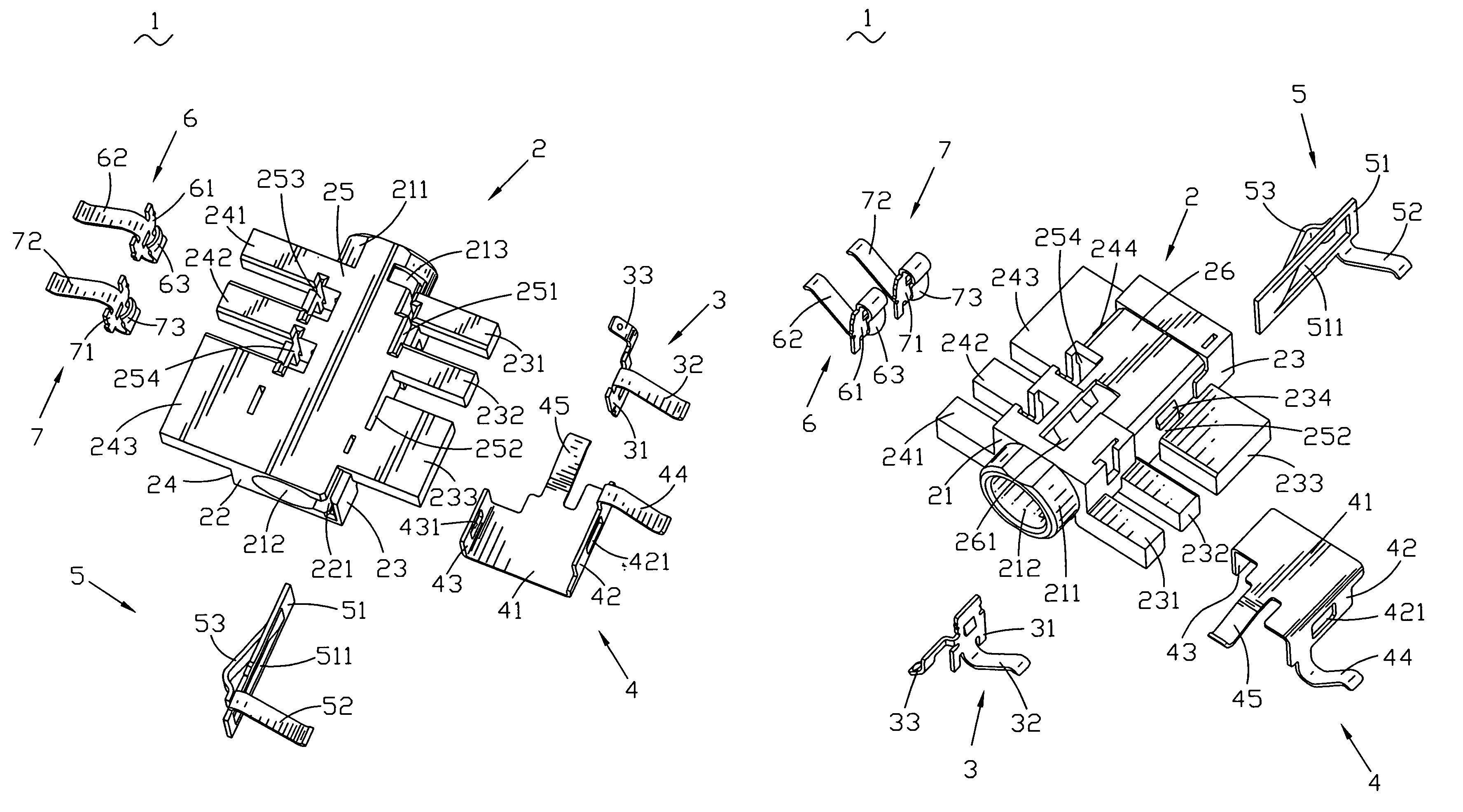
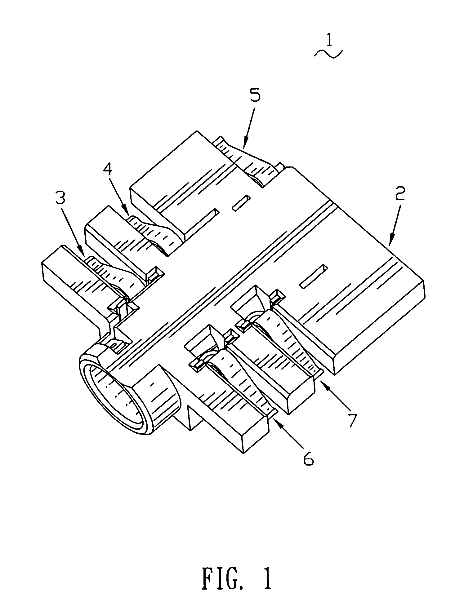
[0016]Referring to FIG. 1, an audio jack connector 1 mating with a complementary plug connector for transmitting audio signals is shown. The audio jack connector 1 includes an insulating housing 2 and a first set of conductive contacts 3, 4, 5, and a second set of conductive contacts 6, 7 being inserted in the insulating housing 2.

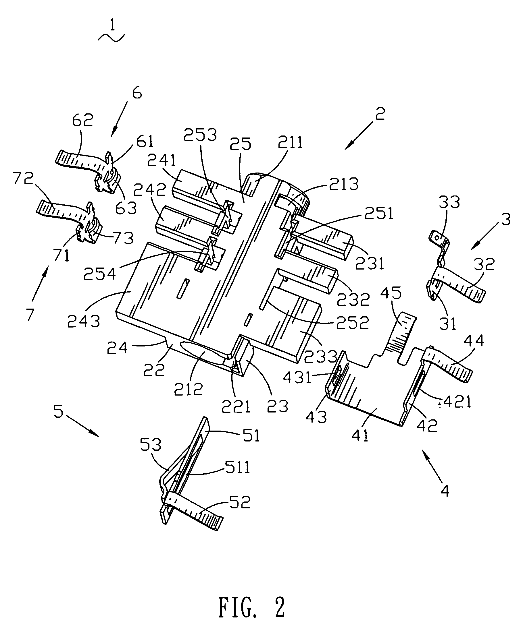
[0017]Referring to FIG. 2 and FIG. 3, the insulating housing 2 has a mating wall 21, a rear wall 22 opposite to the mating wall 21, a top wall 25, two lateral walls 23, 24 extending downwardly from two lateral sides of the tope wall 25, and a bottom wall 26 opposite to the top wall 25. The insulating housing 2 is a rectangular structure body. Two lateral sides of the top wall 25 stretch outwardly to form a plurality of rectangular left wings 231, 232, 233 and right wings 241, 242, 243. The two lateral walls23, 24 are located below the left wings 231, 232, 233 and right wings 241, 242, 243. A top face of each wing 231, 232, 233, 241, 242, 243 is flush with ...


PUM


Abstract

An audio jack connector includes an insulating housing and a first set and a second set of conductive contacts. A plurality of recesses is provided in the insulating housing. Each contact has a fixing portion, a contacting portion and an elastic compressing portion. The first and second sets of conductive contacts are received in the plurality of recesses, the elastic compressing portions of the first set of conductive contacts is located at a middle position of a lateral wall of the insulating housing; the elastic compressing portions of the second set of conductive contacts are located at a middle position of the opposite laterally wall of the insulating housing. While the audio jack connector is assembled with an external printed circuit board having a gap, the audio jack connector embedded into the gap, so the assembly height of the audio jack connector is reduced.

Description

BACKGROUND OF THE INVENTION[0001]1. Field of the Invention[0002]The present invention relates to a connector, and more particularly, relates to an audio jack connector.[0003]2. The Related Art[0004]An audio jack connector is widely used in electronic devices for transmitting audio signals. A conventional audio jack connector includes a plastic housing and a plurality of contacts. The plastic housing has a receiving cavity for receiving a complementary plug connector. Pluralities of recesses, which extend through the receiving cavity, are provided in the plastic housing. Each contact has a contacting portion and a soldering portion. The contacts are received in the recesses, and the contacting portions are revealed in the receiving cavity for electrically connecting the complementary plug while the soldering portions is soldered to an external printed circuit board (PCB).[0005]However, the contacts of the conventional audio jack connector as described above soldered to the external p...

Claims


Application Information

Patent Timeline
IPC IPC(8): H01R24/04H01R24/58
CPCH01R13/41H01R24/58H01R2107/00
Inventor WU, YIN-LUNG
Owner CHENG UEI PRECISION IND CO LTD
Why Eureka
Try Eureka