

An improved receiver
An improved technology for receivers, applied in the field of receivers, can solve the problems of increased processing difficulty, high processing precision requirements, complex molds, etc., and achieve the effects of easy assembly, reduced assembly height, processing cost and processing difficulty
- Summary
- Abstract
- Description
- Claims
- Application Information
AI Technical Summary
Problems solved by technology
Method used
Image

Examples
Embodiment 1
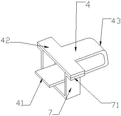
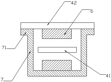
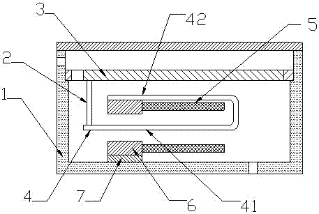
[0026] An improved receiver, including an electromagnetic shielding shell, a sounding unit and an electromagnetic driving unit arranged in the electromagnetic shielding shell, and the electromagnetic driving unit transmits vibration to the sounding unit through a conducting rod; Figure 1-2 As shown, the electromagnetic drive unit includes an armature 4 and an iron core 7. The armature 4 is a bent and formed U-shaped strip plate. The two ends of the U-shaped armature are respectively a vibrating part 41 and a fixed part 42. It is connected with the fixing part 42 through the bending part 43; the iron core 7 is a U-shaped frame formed by bending, and the fixing part 42 of the armature 4 is arranged at the opening end of the U-shaped frame and forms a closed cavity with the U-shaped frame. The vibrating part 41 of the armature 4 passes through the cavity along its own axial direction and partially protrudes from the cavity, such as image 3 As shown, the electromagnetic drive un...
Embodiment 2
[0030] The rest is the same as that of Embodiment 1, except that the two ends of the U-shaped frame are provided with extension parts 71 for fixed connection with the fixing part 42 , and the fixing part 42 is connected with the extension part 71 by riveting.
[0031] Such as Figure 4 As shown, the part of the vibrating part 41 protruding from the cavity is provided with a through hole for connecting the conducting rod 2 , and the conducting rod 2 is passed through the through hole.
[0032] The conducting rod 2 passes through the through hole and is bent to form a hook 21 for fixed connection with the vibrating part 41 to improve the reliability of the connection between the conducting rod 2 and the vibrating part 41 .
Embodiment 3
[0034] The rest is the same as that of Embodiment 2, except that the two ends of the U-shaped frame are provided with extension parts 71 for fixed connection with the fixing part 42 , and the fixing part 42 is bonded to the extension part 71 .
[0035] Such as Figure 5 As shown, the end of the conductive rod 2 for connecting the diaphragm 3 is provided with a bent surface 22 , and the bent surface 22 is bonded to the diaphragm 3 . When the conduction rod 2 and the diaphragm 3 are fixedly connected, it is only necessary to apply glue on the bending surface, and directly bond the diaphragm to the conduction rod, which avoids the need to insert the conduction rod into the installation hole on the diaphragm in the past. The problem of difficult assembly.
PUM
 Abstract
Description
Claims
Application Information