Gearing and power transmission apparatus

a technology of gear transmission and clutch, which is applied in the direction of gearing, mechanical control devices, instruments, etc., can solve the problems of gear jumping out, the shift fork of being undesiredly displaced, etc., and achieve the effect of reducing the number of components, reliable operation and simplifying the structure of the gear transmission mechanism

Inactive Publication Date: 2007-07-10
AISIN AI CO LTD
View PDF8 Cites 33 Cited by
  • Summary
  • Abstract
  • Description
  • Claims
  • Application Information

AI Technical Summary

Benefits of technology

[0019]It is further preferable that the gearing and power transmission apparatus includes a shift and select shaft rotatable about an axis at right angles to the first and second input shafts and movable in an axial direction. In this case, the shift and select member is fixed to the shift and select shaft and has an inner lever that projects in a radial direction. The tip end of the shift and select member can be a tip end of the inner lever. The interlock member can be an inter lock plate mounted on the shift and select shaft to be freely rotatable and not axially movable via side plates between which the inner lever is positioned. The restraining portion can include two pairs of fingers which extend from both side portions of the both side plates of the interlock member so that the pairs of fingers face one another along both inner sides of the notches of the tip ends of the fork heads that are positioned at the neutral position. In this case, the structure of the operation mechanism of the gear transmission mechanisms can be simplified, and the number of components can be reduced. Further, it is possible to achieve a gearing and power transmission apparatus of which operation is reliable and manufacturing cost is economical.

Problems solved by technology

In this case, at a time that a strong external force is applied to each shift fork 61A to 61D, there is a danger of the shift fork of being undesirably displaced from the neutral position to one of the shift positions, or from one of the shift positions to the neutral position In this case, there is a danger of an occurrence of a gear jump out, in which a shift stage, which should actually be established in the transmission, can not be established, or of a double-gear engagement, in which a shift stage, which should not actually be established in the transmission, is undesirably established.

Method used


Image

  • Gearing and power transmission apparatus
  • Gearing and power transmission apparatus
  • Gearing and power transmission apparatus

Examples


Embodiment Construction

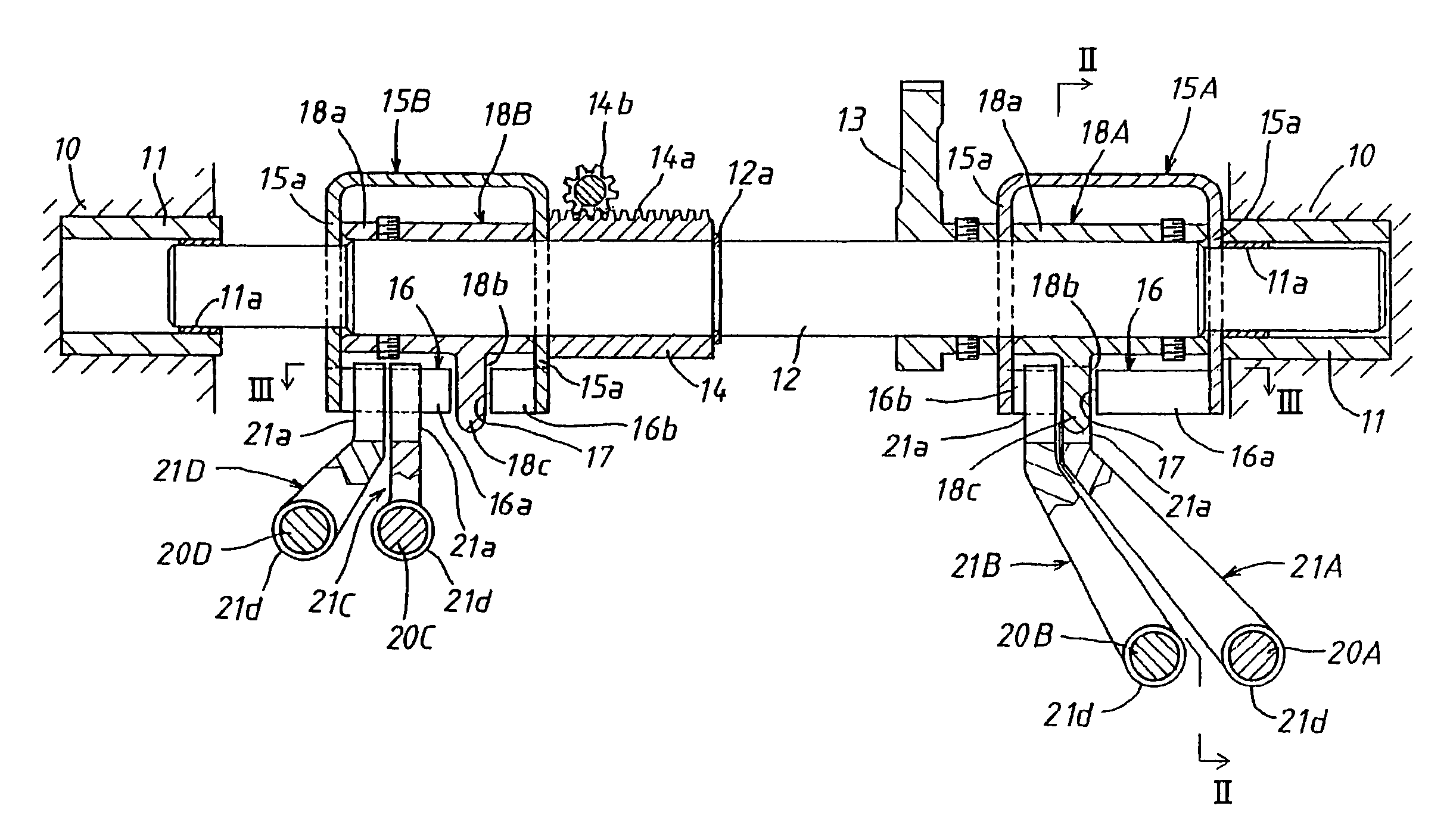
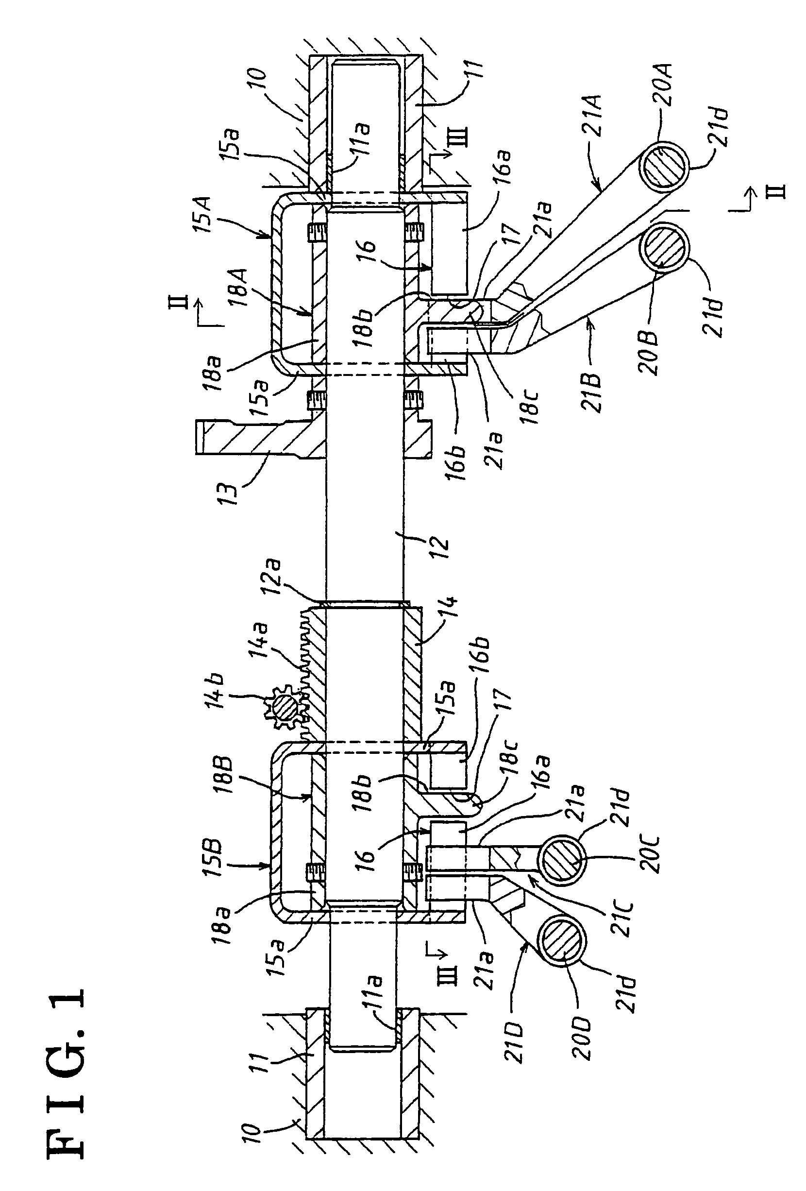
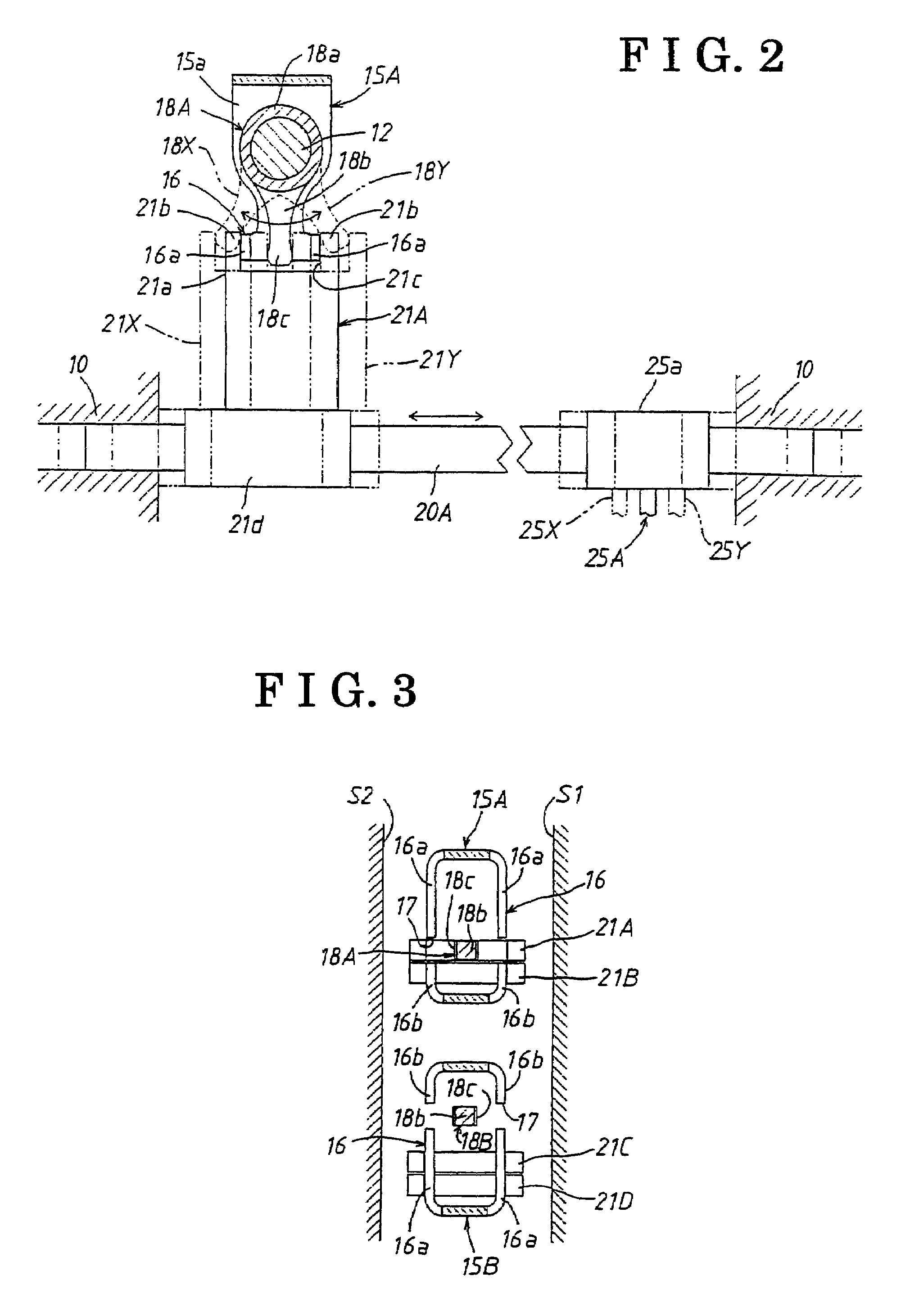
[0034]A gearing and power transmission apparatus according to an embodiment of the present invention is described below with reference to FIGS. 1 to 9. Explanation views for explaining the twin clutch-type gearing and power transmission illustrated in FIGS. 8 and 9 explains a part of an entire structure of the apparatus according to the embodiment of the present invention. The part of the entire structure of this apparatus is identical to the aforementioned description as a background of this present invention. Therefore, detailed description of this apparatus according to the embodiment of the present invention is omitted herein. Described below is an operation mechanism having an interlocking feature, and an entire operation, for putting the first gear transmission mechanism 30A and the second gear transmission mechanism 30B into operation.

[0035]As is illustrated in FIGS. 1 to 3, an operation mechanism having an interlocking feature is configured with a shift and select shaft 12, ...


PUM


Abstract

A transmission apparatus includes an interlock member having a restraining portion movable together with a shift and select member in a right-angled direction and, while fork heads are at neutral positions in the right-angled direction, extending in the right-angled direction along a notch of the tip end of each fork head. The restraining portion has a gap into which the tip end of each fork head extends. A dimensional relationship among an outer span of the tip end of each fork head, an inner span of the notch, an outer span of the restraining portion, an inner span of the restraining portion, a width of the tip end of the shift and select member, and a shift stroke of each fork head is set to be: H2−P1≧0; P2−H1+2S≧0; and H2−2S−I≧0.

Description

CROSS REFERENCE TO RELATED APPLICATIONS[0001]This application is based on and claims priority under 35 U.S.C. §119 with respect to Japanese Patent Application 2004-176587, filed on Jun. 15, 2004, the entire content of which is incorporated herein by reference.FIELD OF THE INVENTION[0002]This invention generally relates to a double clutch-type gearing and power transmission apparatus provided with an interlocking feature, by which occurrences of a double-gear engagement, or of a gear jump out, in a transmission, are capable of being avoided.BACKGROUND[0003]As an automated manual transmission apparatus for a vehicle, such as an automobile, although it has been conventionally believed that a fluid-type torque converter can be generally applied, consideration should be given preferably to that a transmission efficiency for transmitting a driving force of a driving power source, such as an engine, may on occasions be deteriorated due to a slip in transmitting the driving force, the slip ...

Claims


Application Information

Patent Timeline
Patent Type & Authority Patents(United States)
IPC IPC(8): F16H3/28F16H63/32F16H63/20F16H63/34
CPCF16H63/20F16H63/3408F16H3/006F16H2063/025Y10T74/19219F16H2063/202Y10T74/19288Y10T74/20183F16H2063/208
Inventor OGAMI, SHIROTANBA, TOSHIO
Owner AISIN AI CO LTD
Why Eureka
Try Eureka