Method and apparatus for decomposing received symbol signal modulated with bit reflected gray code in bit information

Inactive Publication Date: 2011-05-05
SAMSUNG ELECTRONICS CO LTD +1
View PDF4 Cites 3 Cited by
  • Summary
  • Abstract
  • Description
  • Claims
  • Application Information

AI Technical Summary

Benefits of technology

[0022]According to the embodiments of the present invention, a simple operation structure for complex bitwise decomposition is suggested, and it is effective for signal detection of QAM and PAM signals.

Problems solved by technology

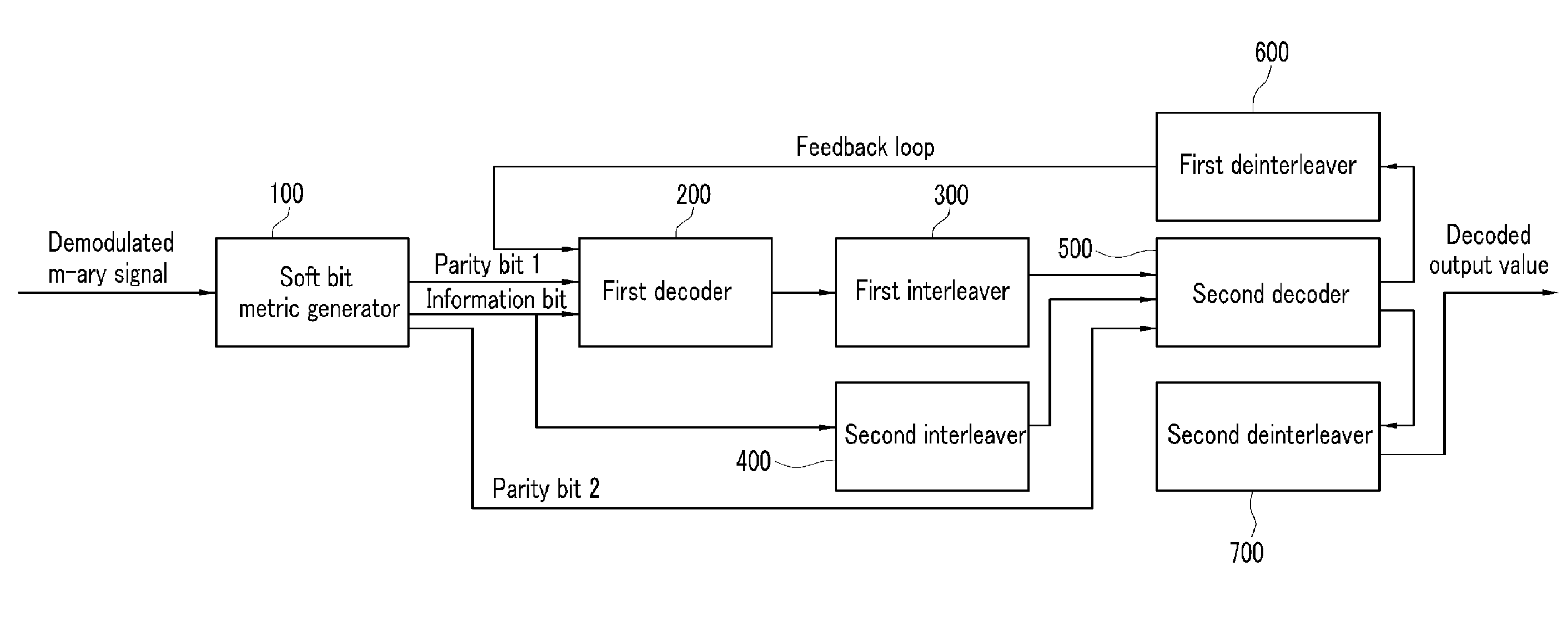
At this time, as represented by Equation 1, as the number of signal points is increased, it becomes more difficult to implement the operation structure due to an exponential operation, and thus complexity is increased.
However, as the number of symbols is increased, to calculate the Max / Min values, many comparison operations are required depending on the number of cases, which causes an increase in implementation complexity.
That is, when Equations 1 and 2 are used, complexity is increased and processing speed becomes low.
1. In general, a memory is used, and as the number of symbols is increased and the quantization level becomes higher, the memory amount is increased. If the quantization level is lowered so as to reduce the memory amount, the performance may be deteriorated. The memory is constantly activated, and accordingly current consumption is increased. An area is required to implement the memory. Particularly, in the case of adaptive modulation, a ROM or a ROM / RAM needs to be used, and an LUT value needs to be changed depending on a signal modulation level M to be used.
However, since the operation structure is a sequential operation structure in which the previous operation result is used to perform a next stage operation, there is a limitation to increase the operation speed for wideband transmission in a fast operation.

Method used


Image

  • Method and apparatus for decomposing received symbol signal modulated with bit reflected gray code in bit information
  • Method and apparatus for decomposing received symbol signal modulated with bit reflected gray code in bit information
  • Method and apparatus for decomposing received symbol signal modulated with bit reflected gray code in bit information

Examples


Embodiment Construction

[0032]In the following detailed description, only certain exemplary embodiments of the present invention have been shown and described, simply by way of illustration. As those skilled in the art would realize, the described embodiments may be modified in various different ways, all without departing from the spirit or scope of the present invention. Accordingly, the drawings and description are to be regarded as illustrative in nature and not restrictive. Like reference numerals designate like elements throughout the specification.

[0033]Throughout this specification, unless explicitly described to the contrary, the word “comprise” and variations such as “comprises” or “comprising” will be understood to imply the inclusion of stated elements but not the exclusion of any other elements. In addition, the terms “-er”, “-or”, “unit”, and “module” described in the specification mean units for processing at least one function and operation, and can be implemented by hardware components or ...


PUM


Abstract

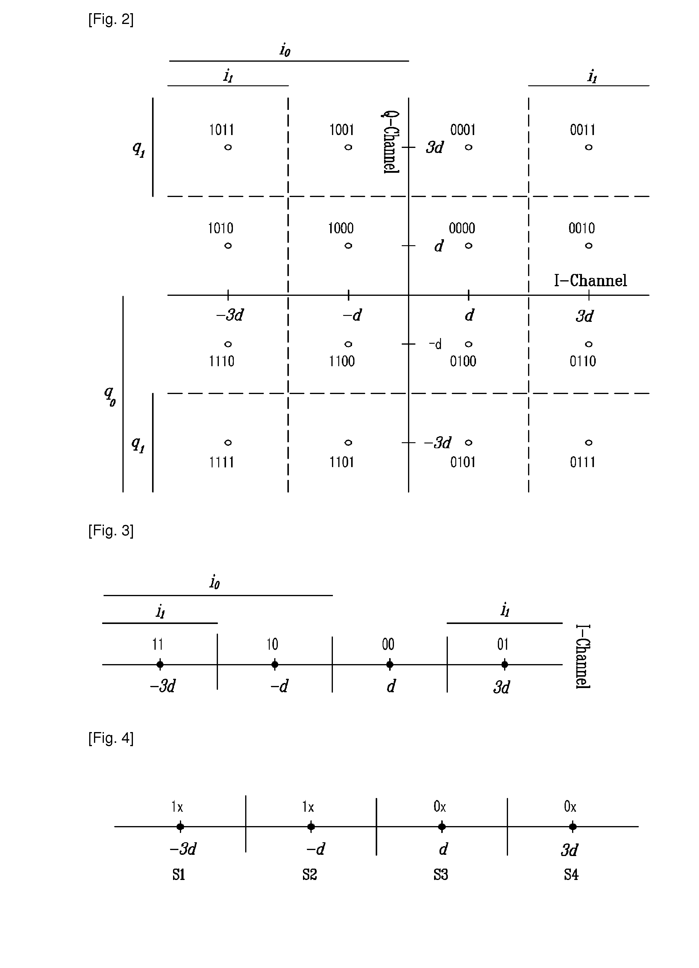
Disclosed is a method and apparatus for composing a received symbol signal modulated with a bit reflected Gray code into bit information. According to an embodiment of the present invention, a positive integer of the received symbol signal having bits is assigned according to the Gray mapping rule, and a sign is determined. A value that is indicative of an arrangement of the bits constituting the received symbol signal is calculated. A boundary value in at least one bit group consisting of the bits constituting the received symbol signal is acquired, and a difference from an absolute value of the received symbol signal is calculated. The received symbol signal is converted into information per bit using a value of the received symbol signal based on the positive integer and the determined sign, the value that is indicative of the bit arrangement, and the difference from the absolute value. Therefore, it is possible to reduce complexity in bitwise decomposition for an iterative decoder inevitably used in a receiver.

Description

TECHNICAL FIELD[0001]The present invention relates to a method and apparatus for decomposing a received symbol signal modulated with a bit reflected Gray code (hereinafter referred to as “BRGC”) into bit information. Particularly, the present invention relates to a method and apparatus for decomposing symbol values, which are used to apply an iterative decoding scheme to a symbol-mapped QAM (quadrature amplitude modulation) signal and a PAM (pulse amplitude modulation) signal with the BRGC, into bit information based on probabilities.BACKGROUND ART[0002]In recent years, advancement of channel codes such as turbo codes and low density parity check (hereinafter referred to as “LDPC”) codes has occurred, communication can now be performed with a low bit error rate at a low signal-to-noise ratio (SNR). Therefore, in a system for mobile communication or satellite communication, high-data rate and high-quality communication can be performed.[0003]In a communication system that uses higher...

Claims


Application Information

Patent Timeline
IPC IPC(8): H04L27/06
CPCH04L25/067H04L1/005H04L27/38
Inventor YU, CHANG WAHNYOON, DONG WEONHYUN, KWANG MINPARK, YOUN OKKIM, DAE HOKIM, JUN-WOOPARK, HYEONG SOOKBAHNG, SEUNG JAEBANG, YOUNG JOSOHN, KYUNG YEOL
Owner SAMSUNG ELECTRONICS CO LTD
Why Eureka
Try Eureka