
Ink-jet line printer and image forming apparatus using the same

a technology of image forming apparatus and printer, which is applied in the field ofinkjet line printer and image forming apparatus using the same, can solve the problems of increased cost, difficult to manufacture a printer with machine fixing accuracy, and prone to defects such as missing dots and slanting lines, etc., and achieves high reliability, easy manufacturing and fixing of the head. , the effect of easy color printing

Inactive Publication Date: 2007-07-10
FUJIFILM BUSINESS INNOVATION CORP
View PDF18 Cites 7 Cited by
  • Summary
  • Abstract
  • Description
  • Claims
  • Application Information

AI Technical Summary

Benefits of technology

[0010]The present invention accordingly provides an ink-jet line printer and an image forming apparatus which protect and recover the surfaces of nozzles of ink-jet heads, even when the ink-jet line printer is of a full-line type.
[0011]The invention has as another object to provide an ink-jet line printer and an image forming apparatus which can easily arrange backup mechanisms for ink-jet heads, even when the ink-jet line printer is of a full-line type.
[0012]The invention has as still another object to provide an ink-jet line printer and an image forming apparatus which can easily and compactly achieve a backup of ink-jet heads, even when the ink-jet line printer is of a full-line type.

Problems solved by technology

The fact that the full-line type ink-jet head 128 is constituted as one unit is a factor contributing to an increase in costs.
However, in the method in which unit heads are connected as in FIG. 34, or in the shuttle head shown in FIG. 35, if the fixing accuracy of the unit heads is not set at a high level, defects in printing such as missing dots and slanting of lines tend to occur.
In general, it is extremely difficult to manufacture a printer with a machine fixing accuracy of this order.
Furthermore, in an ink-jet head, defects easily occur in the spraying of ink particles, as a result of the clogging up of nozzles and the mixing of ink and air bubbles.
However, installation of a backup mechanism for recovering a line head or a shuttle head, of defects in the spraying of ink particles caused by the clogging up of nozzles or by the mixing of ink and air bubbles, itself requires a home position for the entire head.
There is accordingly a risk that the apparatus may need to be increased in size, or may become unnecessarily complicated.

Method used


Image

  • Ink-jet line printer and image forming apparatus using the same
  • Ink-jet line printer and image forming apparatus using the same
  • Ink-jet line printer and image forming apparatus using the same

Examples


Embodiment Construction

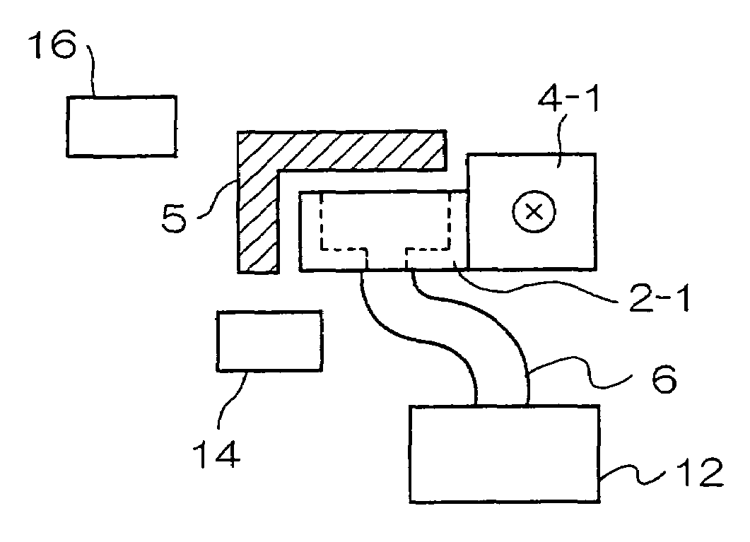
[0074]Embodiments of the present invention will be described in the order named: an ink-jet line printer, an image forming apparatus, control of the ink-jet line printer, another ink-jet line printer, alternating control of arrangement of ink-jet heads, positional adjustment of ink-jet heads, and other embodiments.

[Ink-Jet Line Printer]

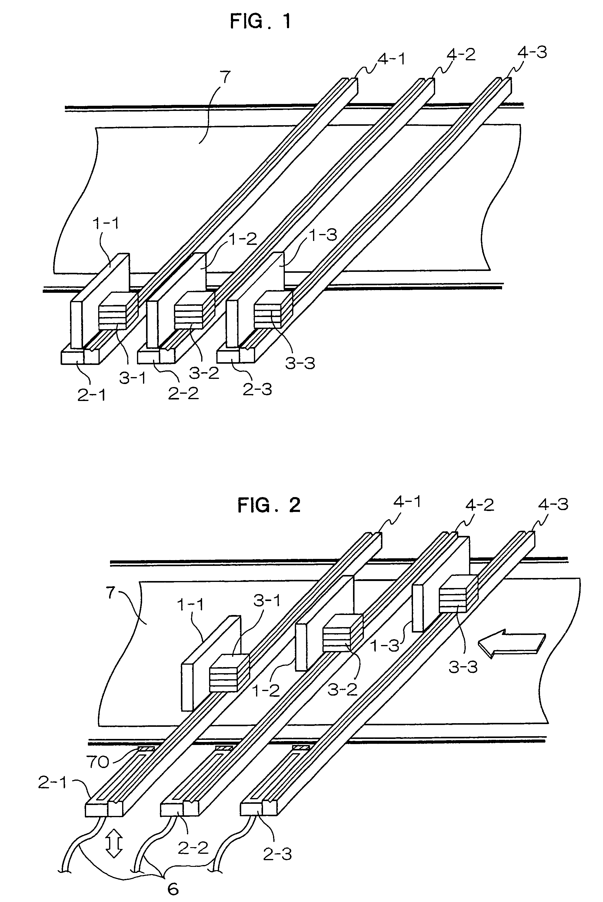
[0075]FIGS. 1 and 2 are diagrams showing configurations of an ink-jet line printer. FIG. 1 shows a state in which ink-jet heads are located at a home position, and FIG. 2 shows a state in which the ink-jet heads are located at a printing position.

[0076]As shown in FIG. 1, three guide rails 4-1 to 4-3 are arranged in the width direction of a printing medium 7 such as a sheet of paper. Stages 3-1 to 3-3 to which ink-jet heads 1-1 to 1-3 are fixed are arranged on the guide rails 4-1 to 4-3, respectively. The ink-jet heads 1-1 to 1-3 are arranged on the stages 3-1 to 3-3, respectively, such that the surfaces of the nozzles face downward. The stages 3-1 to...


PUM


Abstract

An ink-jet line printer (30) is constituted by multiple ink-jet heads (1-1 to 1-3). Actuators (3-1 to 3-3) are arranged so as to be moved between a home position and a print position, and backup mechanisms (2-1 to 2-3) are arranged at home positions. In this ink-jet line printer, the ink-jet heads can be protected and recovered by backup mechanisms, thus making high-speed continuous printing possible. Even though the backup mechanisms are incorporated, a compact apparatus can still be achieved.

Description

TECHNICAL FIELD[0001]The present invention relates to an ink-jet line printer which sprays out ink to perform printing and an image forming apparatus using the ink-jet line printer and, more particularly, to an ink-jet line printer which uses an ink-jet head which performs printing over one line at the same time, and an image forming apparatus using the ink-jet line printer.PRIOR ART[0002]Since an ink-jet printer sprays out, from a nozzle, ink contained in an ink chamber to perform printing, a simple structure can be achieved, and color printing can be easily performed by changing the colors of inks in the ink chamber.[0003]A serial type printer is commonly used as such an ink-jet printer. In a serial type ink-jet printer, an ink-jet head moves along a stay shaft extending from a home position (a standby position or a capping position). The stay shaft sets a main scanning direction such that the surface of a nozzle of an ink-jet head and the printing paper are horizontal. While movi...

Claims


Application Information

Patent Timeline
Patent Type & Authority Patents(United States)
IPC IPC(8): B41J2/165B41J2/14B41J2/155B41J2/18
CPCB41J2/14274B41J2/155B41J2/165B41J2/16585B41J2/16588B41J2/18
Inventor SANPEI, KOICHIMORI, MITSUHIROIWAISHI, AKIRANAKAMURA, SHIGEYOSHITATENO, KATSUMI
Owner FUJIFILM BUSINESS INNOVATION CORP
Learn More