Tangential mixer and method

a mixer and tangential technology, applied in the field of internal combustion engines, can solve the problems of increasing the pressure loss in the intake system of the engine, increasing the fuel consumption, and reducing the efficiency of the engin

Active Publication Date: 2007-07-17
INT ENGINE INTPROP CO LLC
View PDF9 Cites 52 Cited by
  • Summary
  • Abstract
  • Description
  • Claims
  • Application Information

AI Technical Summary

Problems solved by technology

Such methods, although typically fairly effective, have the disadvantage of increasing pressure losses in the intake system of the engine as a result of increased turbulence in the intake air or in the intake mixture.
Increased pressure losses in the intake system of an engine leads to decreased engine efficiency and increased fuel consumption.

Method used


Image

  • Tangential mixer and method
  • Tangential mixer and method
  • Tangential mixer and method

Examples


Embodiment Construction

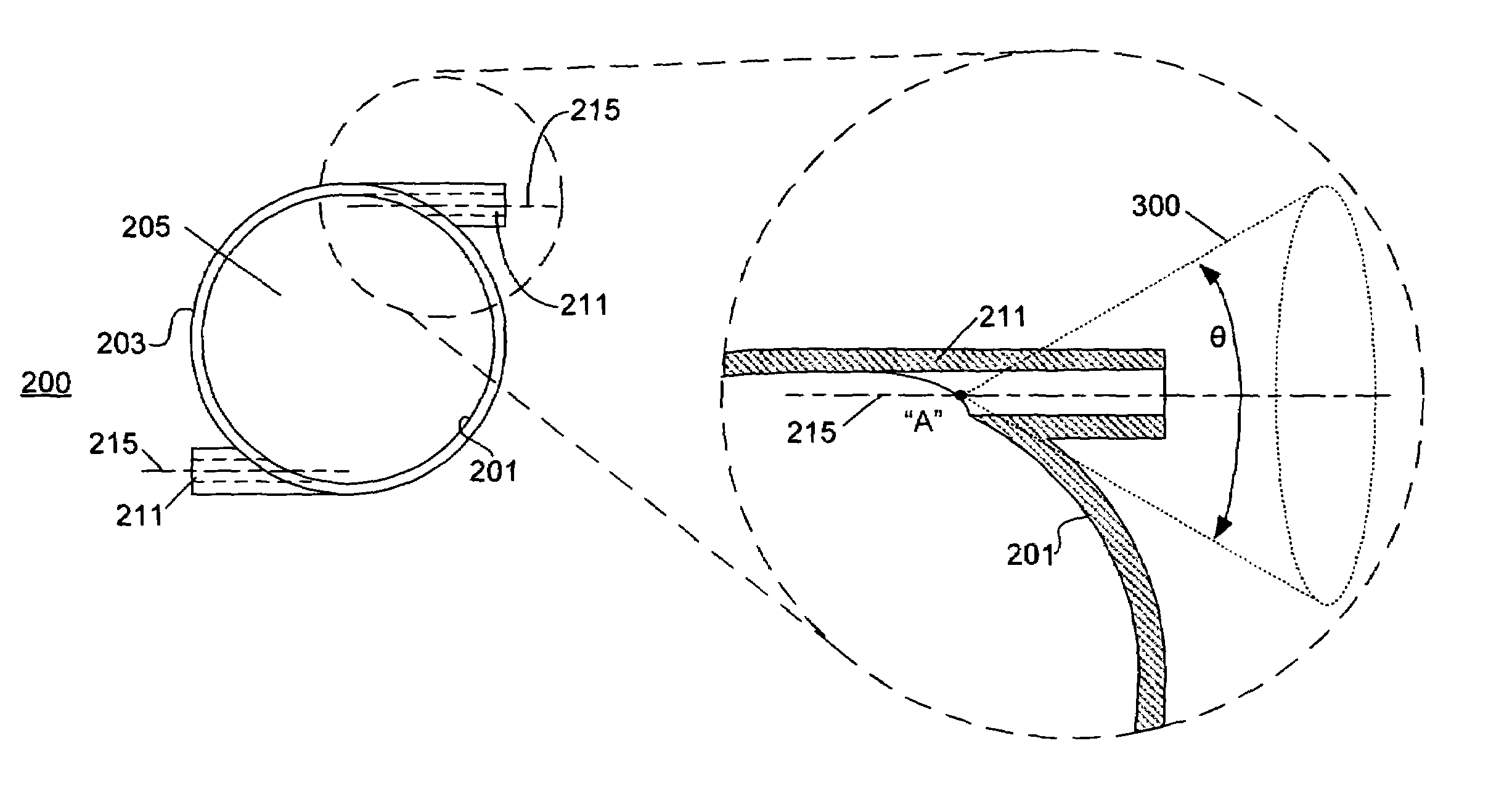
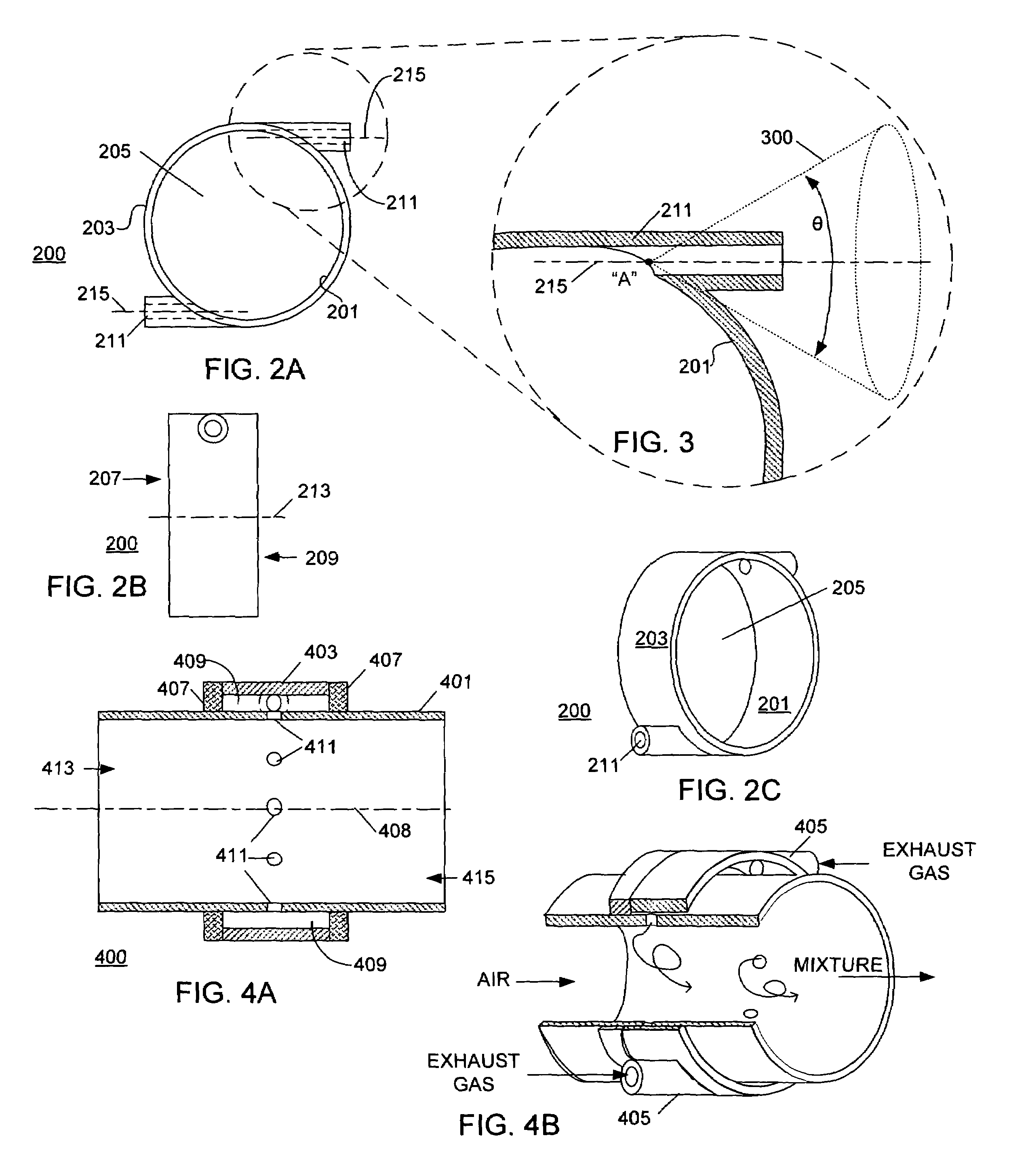
[0019]The following describes an apparatus for and method of mixing recirculated exhaust gas with intake air in an engine having an EGR system, to yield a homogeneous mixture of exhaust gas and intake air. A tangential flow mixer is placed at a junction where the exhaust gas and intake air meet to effectively mix exhaust gas and intake air and yield a homogeneous mixture. The tangential flow mixer does not increase pressure losses in the intake air system, does not increase fuel consumption and does not lower engine efficiency.

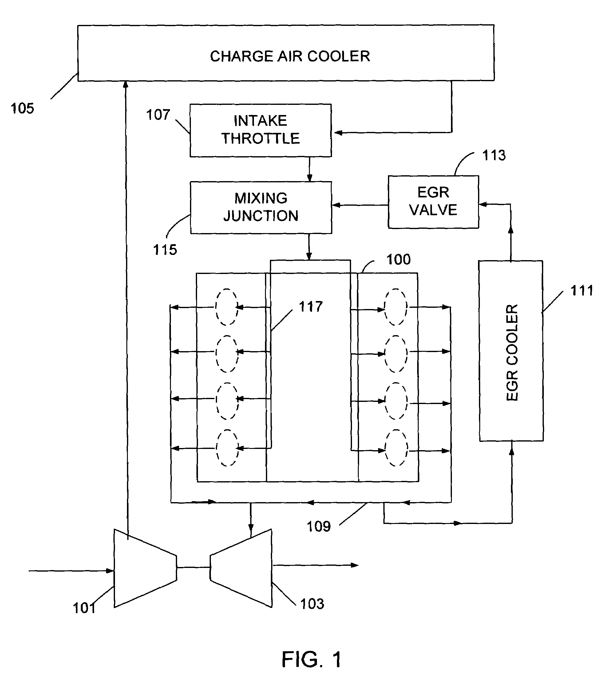
[0020]A block diagram of an engine having a high-pressure EGR system is shown in FIG. 1. A base engine 100 contains a plurality of cylinders housed in an engine block. A compressor 101 is connected to an air cleaner (not shown) and a turbine 103. An outlet of the compressor 101 is connected to a charge cooler 105, which in turn is connected to an intake throttle valve 107. The turbine 103 is connected to an exhaust system 109. The exhaust system 109 is connect...


PUM


Abstract

An apparatus includes a tangential mixer (200) having an air inlet (207) and a mixture outlet (209). A bore (205) has a bore centerline (213) and a bore perimeter (201). At least one gas inlet (211) has an inlet centerline (215) oriented tangentially to the bore perimeter (201). The inlet centerline (215) is within a cone (300). The cone (300) has a vertex point “A” on the inlet centerline (215).

Description

FIELD OF THE INVENTION[0001]This invention relates to internal combustion engines, including but not limited to engines having Exhaust Gas Recirculation (EGR) systems.BACKGROUND OF THE INVENTION[0002]Most internal combustion engines have some type of emission control devices. One type, common to many engines, is recirculation of exhaust gas from an exhaust system to an intake system of the engine. A high pressure EGR system recirculates exhaust gas typically from upstream of a turbine, or other similar device, to downstream of a compressor. Other systems recirculate gas at a low pressure, and are called low-pressure systems. An engine having a high-pressure EGR system has a junction somewhere in the air intake system where EGR gas and intake air mix to form a mixture. The mixture of exhaust gas and intake air is consumed during engine operation.[0003]Providing each cylinder of an internal combustion engine with a homogeneous mixture of exhaust gas and air is advantageous for operati...

Claims


Application Information

Patent Timeline
Patent Type & Authority Patents(United States)
IPC IPC(8): F02M25/07F02B47/08F02M29/00F02B33/44
CPCF02M25/0703F02M25/0707F02M25/0722F02M35/10222F02M25/0732F02M25/0744F02M35/116Y02T10/121F02M26/12F02M26/05F02M26/19F02M26/24F02M26/38
Inventor ZUKOUSKI, RUSSELL P.
Owner INT ENGINE INTPROP CO LLC
Why Eureka
Try Eureka