Agricultural bale accumulator

a bale accumulator and agricultural technology, applied in the field of agricultural machinery, can solve the problems of patents not revealing the attachment of the extension table to the main bale-receiving table, the lack of direct support for the extension table and the bale is not directly supported

Inactive Publication Date: 2007-07-24
SPANIOL PHILLIP G +2
View PDF11 Cites 13 Cited by
  • Summary
  • Abstract
  • Description
  • Claims
  • Application Information

AI Technical Summary

Problems solved by technology

However, U.S. Pat. Nos. 4,961,679 and 4,955,774 do not disclose a support system which contacts the extension table at a location beyond a side of a chassis to which the extension table is attached.
Therefore, the extension table does not have any direct support for a bale accumulated thereon from either the chassis or the ground.
A lack of direct support for the extension table places all the stress due to the weight of a bale on the hinge which may weaken or break over time under normally rigorous field conditions.
These patents also do not disclose attaching the extension table to the main bale-receiving table.
These patents also do not disclose a bale discharge module for moving the main bale-receiving table between a bale accumulating position and bale discharging position, wherein the main bale-receiving table is in a horizontal position and an inclined position, respectively, relative to the chassis.
Therefore, these patents do not teach or suggest a need for supporting an extension table, at a location beyond a side of the load bed to which the extension table is attached, when the extension table is in the unstowed position and when the load bed is in a bale accumulating position and / or a bale discharging position relative to a main frame.
However, U.S. Pat. No. 4,844,675 does not disclose a purpose for the extensions when unfolded to a position coplanar with the associated tables.
This patent also does not disclose a support system that contacts the extension at a location beyond the side of the table to which the extension is attached.
Therefore, the extension does not have any direct support for a partial bale that may be accumulated thereon from either a main frame or the ground.
A lack of direct support for the extension places all the stress due to the weight of a partial bale on the hinge that may weaken or break over time under normally rigorous field conditions.
Further, this patent does not teach or suggest a need for supporting the extension, at a location beyond the side of the table to which the extension is attached, when the extension is m the unstowed position and when the table is in the bale accumulating position and / or the bale discharging position.
However, Holescher's bale accumulator Model 1030 is limited to a bale accumulation capacity of three bales and to a bale discharge capacity of two bales.
However, each one of Case IH Corporation's bale accumulator Model 8576 and the GB 2 297 944A publication does not disclose a support system which contacts the extension table, at a location beyond the side of the load bed to which the extension table is attached, when the extension table is in the unstowed position and when the load bed is in the bale accumulating position and / or the bale discharging position.
Therefore, the extension table does not have any direct support for a bale that may be accumulated thereon from either a main frame or the ground.
A lack of direct support for the extension table places all the stress due to the weight of a bale on a hinge that may weaken or break over time under normally rigorous field conditions.

Method used


Image

  • Agricultural bale accumulator
  • Agricultural bale accumulator
  • Agricultural bale accumulator

Examples


first embodiment

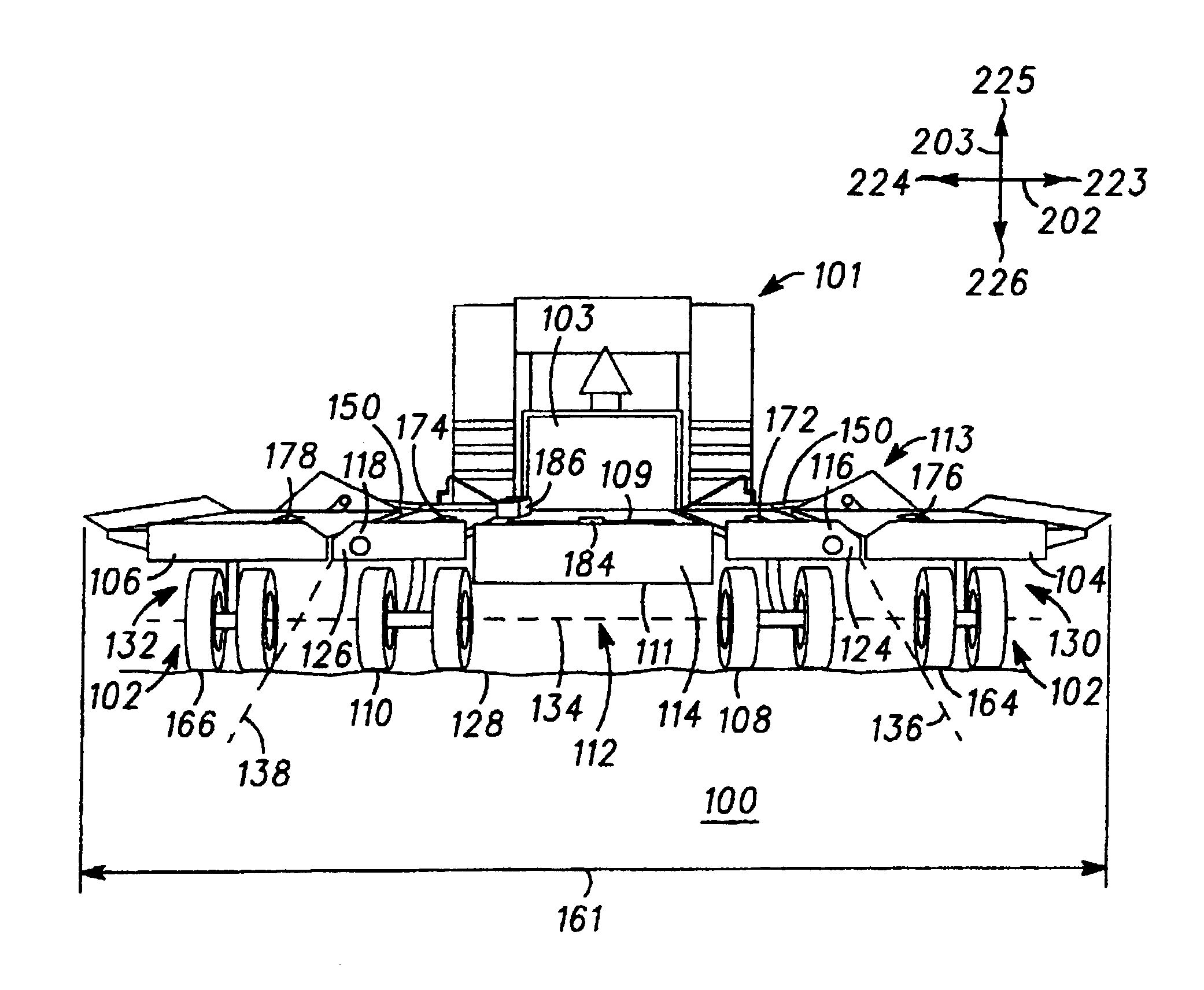
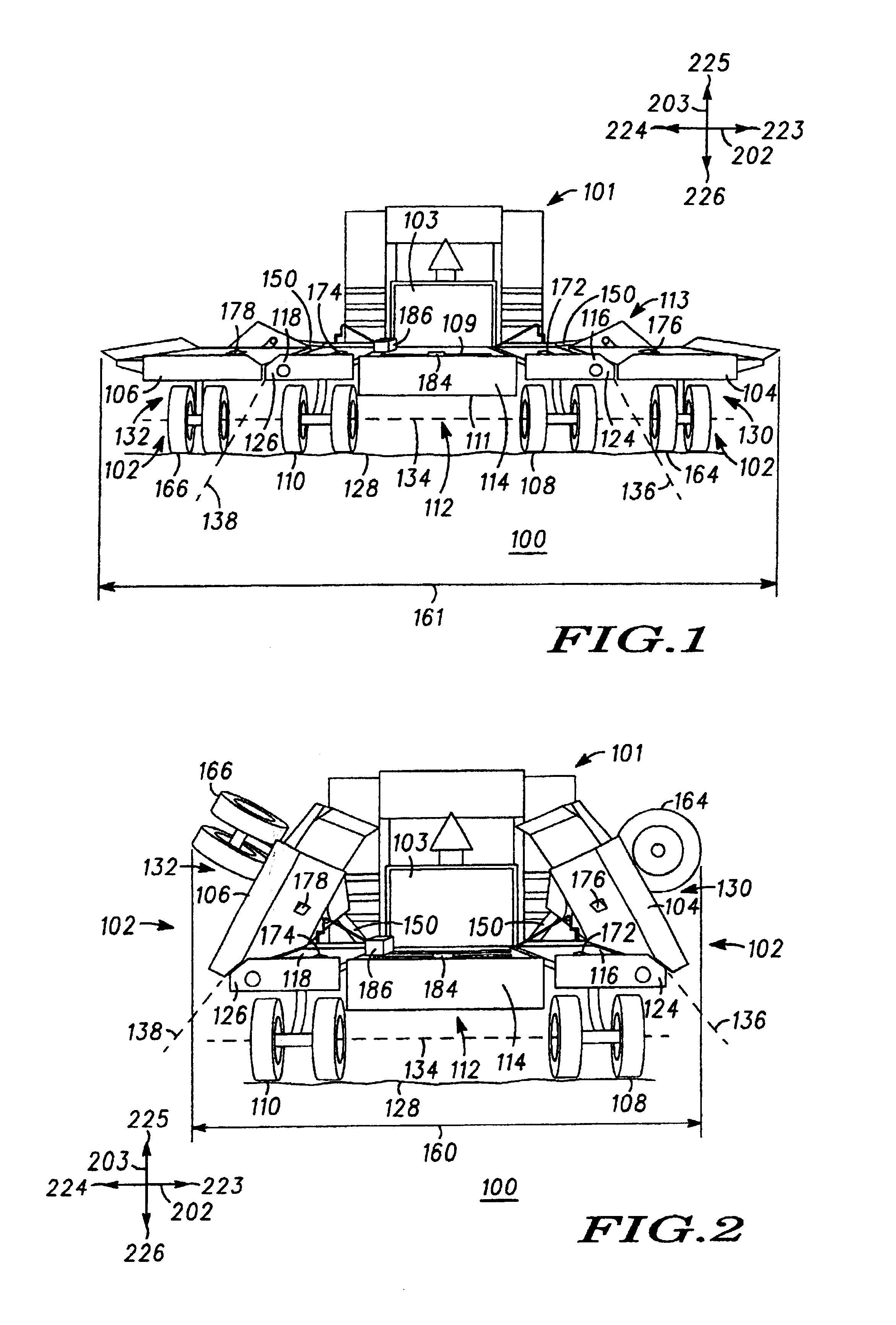
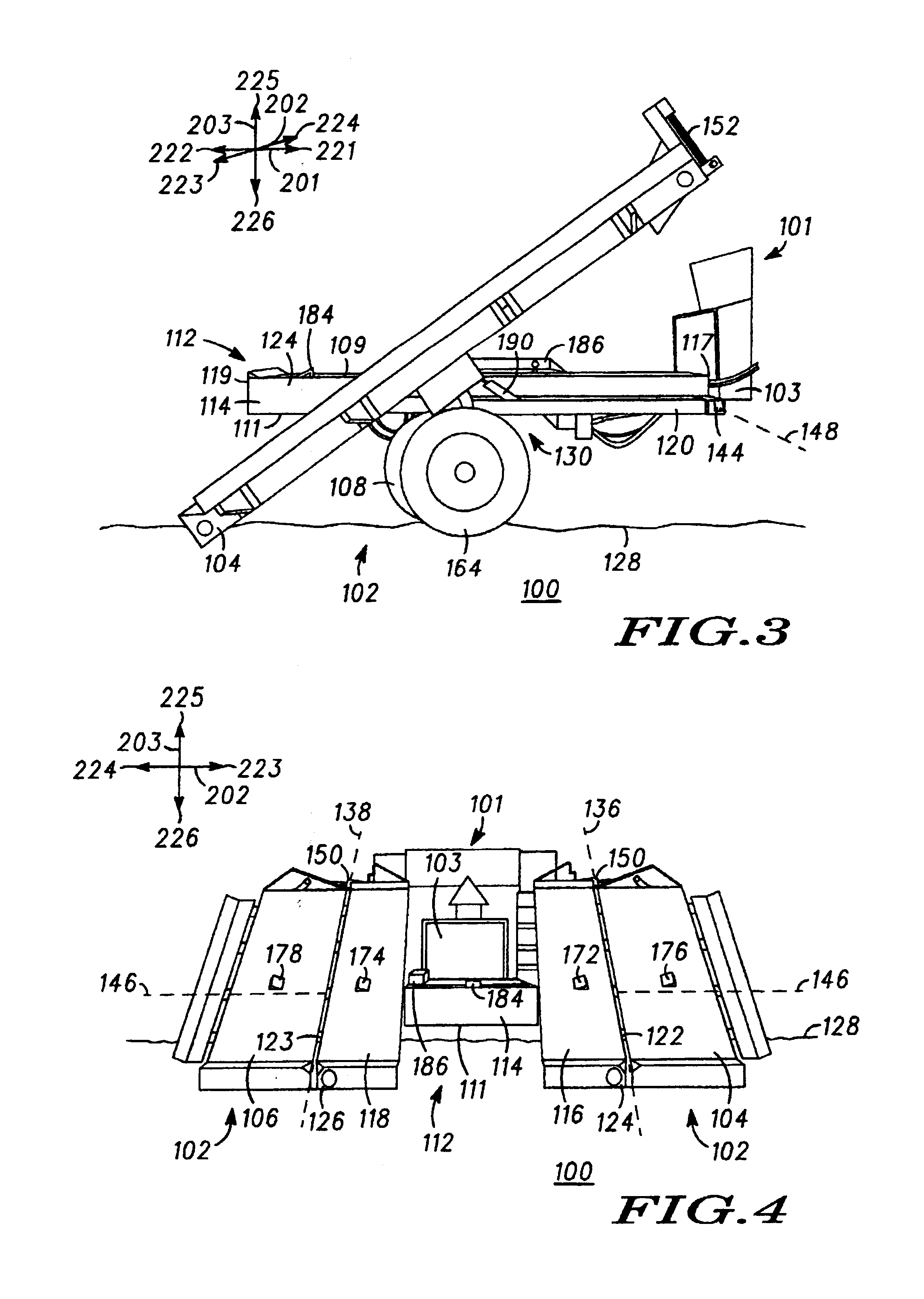
[0081]In the first embodiment as shown in FIGS. 1 through 10, the first extension table support system 130 supports the first extension table 104 from at least one of the base module 112 and the ground surface 128 the when the portion 116 and 118 of the load bed 113 is in at least one of the bale accumulating position and the bale discharging position. It is especially important to note that when the portion 116 and 118 of the load bed 113 is moved to the bale discharging position about the pivot axis 146, as shown in FIGS. 3, 4, 13 and 14, there is a large amount of space between the portion 116 and 118 of the load bed 113 and the main frame 120. In the bale discharging position, the portion 116 and 118 of the load bed 113 is supported from the main frame 120 with the hydraulic cylinder 190 which is used to forcibly tilt the portion 116 and 118 of the load bed 113 relative to the main frame 120. Likewise, the first 104 and second 106 extension tables attached to the portion 116 and...

third embodiment

[0088]In the first and third embodiment of the load bed extension module 102, as shown in FIGS. 1-10, 24 and 25, respectively the first extension table support system 130 includes a first support wheel 164 connected to the first extension table 104 and moveable with the first extension table 104 when the first extension table 104 moves between the stowed position and the unstowed position. The first support wheel 164 contacts the ground surface 128 to support the first extension table 104 from the ground surface 128. The first support wheel 164 advantageously provides support along the vertical axis 203 in the upward direction 225 relative to the first extension table 104.

[0089]In the fourth, sixth, seventh, eleventh, and twelfth embodiments of the load bed extension module 102, as shown in FIGS. 26 and 27, 30 and 31, 32 and 33, 39, and 40, respectively, the support wheel is connected to the moveable frame member of the fourth frame extension member 192 and will be described in furt...

second embodiment

[0103]The second embodiment, as shown in FIGS. 11-23, illustrates an alternate truss member 141 of the first frame extension member 140. The truss member 141 is shown in FIGS. 11, 12 and 14 at the rear side 119 of the bale accumulator 100. Preferably, the truss member 141 is a metal block attached to the rear side of the first extension table 104 or the second extension table 106 and makes contact with the rear side of the right side load bed 116 or the left side load bed 118, respectively, at a location beyond the first hinge axis 136 or the second hinge axis 138, respectively. The mechanical interference between these corresponding elements advantageously supports the first extension table 104 and the second extension table 106 from the load bed 113.

3. Second Frame Extension Member (ex: cylinder)

[0104]The collapsible cylinder of the second frame extension member 150 is described with reference to the first, second, and ninth embodiments of the load bed extension module 102, as sho...


PUM


Abstract

An agricultural bale accumulator (100) includes a load bed (113) and a load bed extension module (102). The load bed extension module (102) includes an extension table (104) pivotally connected to a side (124) of a load bed (113) by a hinge mechanism (122). The hinge mechanism (122) permits the load bed extension module (102) to move relative to the load bed (113) between a stowed position, perpendicular to the load bed (113), and an unstowed position, co-planar with a load bed (113) and adjacent to the side (124) of the load bed (113). The agricultural bale accumulator (100) has a first lateral width dimension (160) when the first extension table (104) is in the stowed position to provide a first bale accumulating capacity and a first bale discharging capacity. The agricultural bale accumulator (100) has a second lateral width dimension (161), greater than the first lateral width dimension (160), when the first extension table (104) is in the unstowed position to provide a second bale accumulating capacity and a second bale discharging capacity, greater than the first bale accumulating capacity and the second bale discharging capacity, respectively. Optionally, an extension table support system (130) may also be used to provide additional support for the extension table (104).

Description

CROSS REFERENCE TO RELATED APPLICATIONS[0001]The present application is a continuation application filed under 37 C.F.R. 1.53(b) and 35 U.S.C. 120 of U.S. application having Ser. No. 09 / 486,902, now U.S. Pat. No. 6,425,235, which was a national stage application filed under 35 U.S.C. 371 of international patent application having Ser. No. PCT / US97 / 15574, filed on Sep. 2, 1997, by Phillip G. Spaniol, Stephen J. Spaniol and Kevin D. Kaschke, and entitled “Agricultural Bale Accumulator Having A Load Bed Extension Module.”FIELD OF THE INVENTION[0002]The present invention relates generally to agricultural machinery for harvesting crop material such as hay, straw, grass or the like, and more particularly the present invention relates to an agricultural bale accumulator having a load bed extension module.BACKGROUND OF THE INVENTION[0003]A continuing trend to achieve an efficient farming operation and to decrease manual labor provides the need for efficient and capable agricultural machiner...

Claims


Application Information

Patent Timeline
Patent Type & Authority Patents(United States)
IPC IPC(8): A01D75/04A01D85/00
CPCA01D85/005A01D2085/007A01D2085/008
Inventor SPANIOL, PHILLIP G.SPANIOL, STEPHEN J.KASCHKE, KEVIN D.
Owner SPANIOL PHILLIP G
Why Eureka
Try Eureka