Valve operating mechanism of internal combustion engine

a technology of internal combustion engine and operating mechanism, which is applied in the direction of valve drive, machine/engine, auxillary lubrication, etc., can solve the problem of shortening the life of the valve operating mechanism

Inactive Publication Date: 2007-07-24
HITACHI LTD
View PDF12 Cites 33 Cited by
  • Summary
  • Abstract
  • Description
  • Claims
  • Application Information

AI Technical Summary

Benefits of technology

[0008]It is therefore an object of the present invention to provide a valve operating mechanism of an internal combustion engine, which is free of the above-mentioned drawback.

Problems solved by technology

If the oil supply to such moving parts is not suitably carried out, smoothed operation of the moving parts is not effected and furthermore, the parts are subjected to a severe frictional wear which would shorten the life of the valve operating mechanism.

Method used


Image

  • Valve operating mechanism of internal combustion engine
  • Valve operating mechanism of internal combustion engine
  • Valve operating mechanism of internal combustion engine

Examples


first embodiment

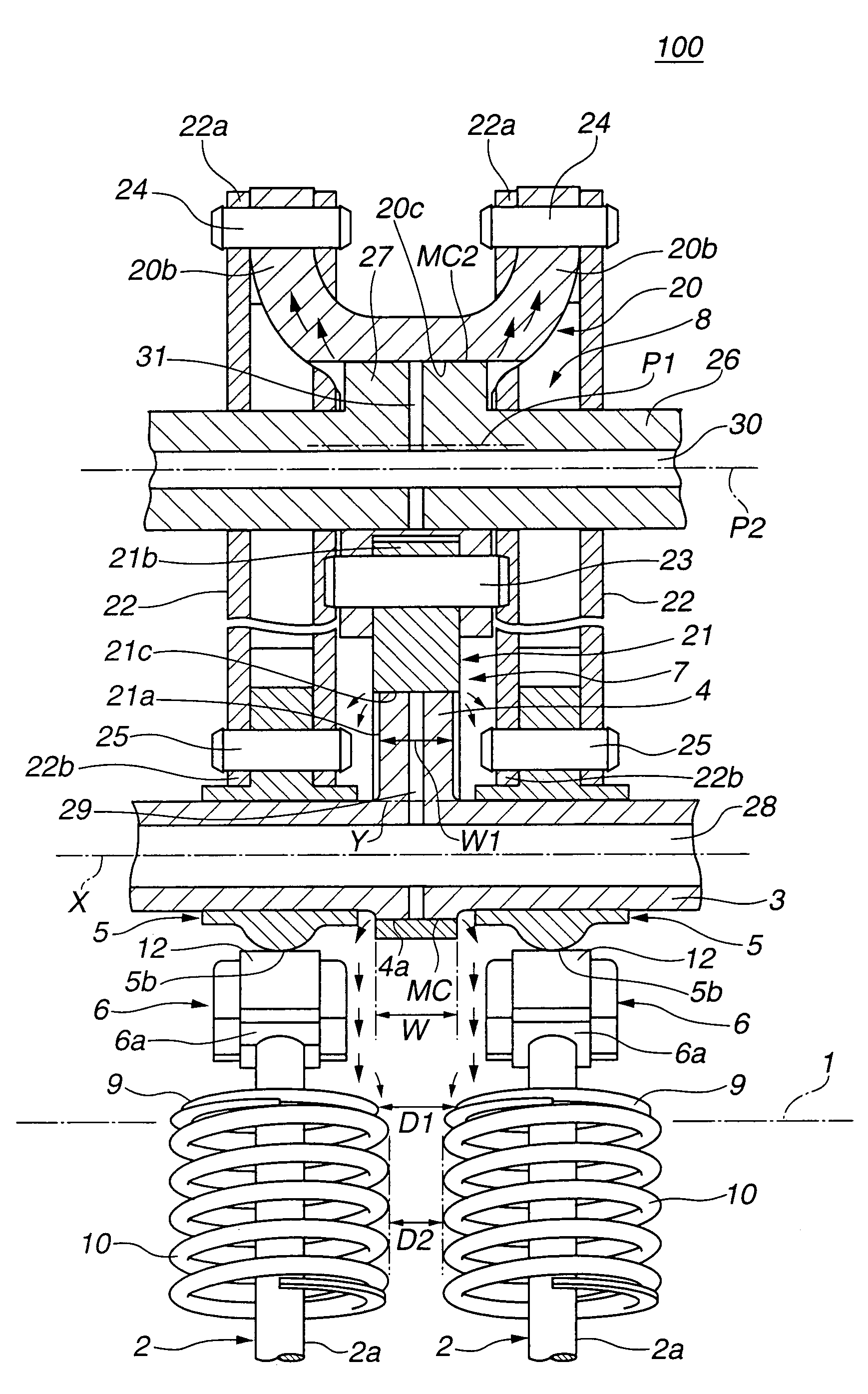
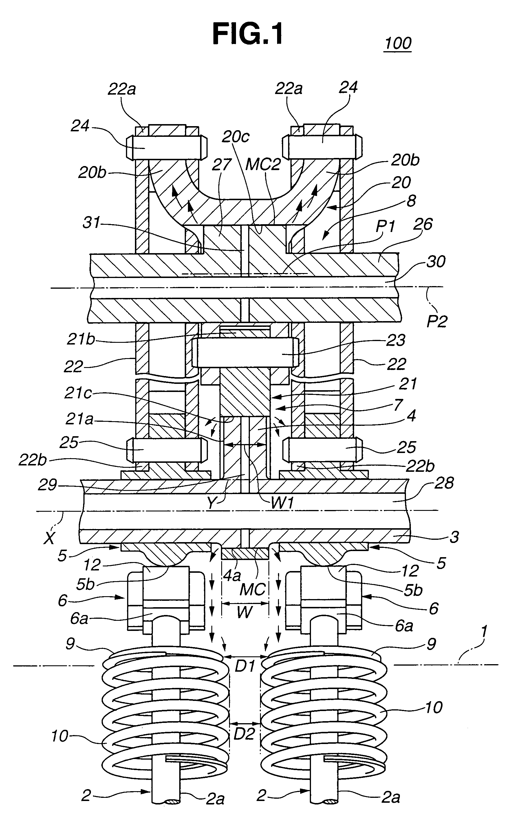
[0039]Referring to FIGS. 1 to 11, particularly FIGS. 1 to 5, there is shown a valve operating mechanism 100 of an internal combustion engine, which is the present invention.

[0040]As is best seen from FIGS. 1, 2 and 3, valve operating mechanism 100 of this first embodiment is constructed to control a pair of intake valves 2 and 2 (viz., engine valves) of an internal combustion engine. Intake valves 2 and 2 are slidably held by a cylinder head 1 of the engine through valve guides (not shown).

[0041]Positioned above intake valves 2 and 2 is a hollow drive shaft 3 that is a part of the valve operating mechanism 100 and extends in an axial direction of the engine.

[0042]As is seen from FIG. 1, a drive cam 4 is integrally formed on drive shaft 3 at a portion just above the corresponding cylinder.

[0043]A pair of swing cams 5 and 5 are rotatably held by drive shaft 3 at axially opposite positions of the shaft 3 relative to drive cam 4. These swing cams 5 and 5 function to cause intake valves ...

second embodiment

[0121]Referring to FIGS. 12 and 13, there is shown a valve operating mechanism 200 of an internal combustion engine, which is the present invention.

[0122]As is best seen from FIG. 12, in this second embodiment 200, arm portion 21b of link arm 21 and first arm portion 20a of rocker arm 20 are connected through a so-called pivot structure. That is, arm portion 21b is formed with a semispherical head 32 that is slidably received in a semispherical recess 33 formed in first arm portion 20a of rocker arm 20.

[0123]Furthermore, a return spring 35 is compressed between first arm portion 20a and a rocker cover 34 so that rocker arm 20 is biased to turn in a clockwise direction in FIG. 12, that is, in a direction to press semispherical recess 33 of rocker arm 20 against semispherical head 32 of link arm 21.

[0124]Due to the nature of the pivotal structure as mentioned hereinabove, a positional misregistration between link arm 21 and rocker arm 20 is sufficiently absorbed and thus much improved...

third embodiment

[0126]Referring to FIG. 14, there is shown a valve operating mechanism 300 of an internal combustion engine, which is the present invention.

[0127]As is well understood when comparing FIG. 14 and FIG. 4, in this third embodiment 300, the arrangement of the unit including movement transmission mechanism 7 and valve lift control mechanism 8 relative to swing arms 6 and 6 is opposite to the arrangement of the first embodiment 100.

[0128]Thus, in this third embodiment 300, cam nose portion 5c of each swing cam 5 is positioned near pivot member 11, and link arm 21 is positioned near valve stems 2a and 2a of corresponding intake valves 2 and 2. Due to this neighboring arrangement of the parts, the lubricating oil from the minute clearance “MC” between link arm 21 and drive cam 4 is easily splashed toward spring retainers 9 and 9 and valve springs 10 and 10 to lubricate the same. Furthermore, the lubricating oil flowing down along cam surfaces 5b and 5b of swing cams 5 and 5 falls onto swing...


PUM


Abstract

A valve operating mechanism of an internal combustion engine, comprises a drive cam rotatable with and eccentric to a drive shaft; a link arm having a circular opening in which the drive cam is rotatably received, so that rotation of drive cam about an axis of the drive shaft produces a swing movement of the link arm; a pair of swing cams swingably disposed on the drive shaft at both sides of the drive cam, the swing cams being connected through a movement transmission mechanism to the link arm to be swung when the link arm is subjected to the swing movement; a pair of swing arms respectively actuated by the swing cams for carrying out an open / close operation of a pair of engine valves; a pair of spring retainers respectively provided by the pair of engine valves; and a pair of valve springs respectively held by the spring retainers and biasing the engine valves in a close direction. A lubricating oil passage is formed in the drive cam. The oil passage has one end exposed to an oil feeding passage formed in the drive shaft and the other end exposed to a minute clearance defined between a cylindrical outer surface of the drive cam and a cylindrical inner surface of the circular opening of the link arm.

Description

BACKGROUND OF THE INVENTION[0001]1. Field of the Invention[0002]The present invention relates in general to valve operating mechanisms of internal combustion engines, and more particularly to the valve operating mechanisms of a type having an improved lubricating oil supply arrangement that provides mutually contacting portions of moving parts with a sufficient lubricating oil.[0003]2. Description of the Related Art[0004]In order to clarify the task of the present invention, one conventional valve operating mechanism of an internal combustion engine will be briefly described before describing the detail of the present invention. The valve operating mechanism is disclosed in P2003-500602A (WO00 / 073635).[0005]The valve operating mechanism of the publication is of a so-called “desmodromic cam driven variable valve (VVT)” type which comprises generally a camshaft that is driven by a crankshaft, valve opening and closing cams that are mounted on the camshaft and a control member that is ...

Claims


Application Information

Patent Timeline
Patent Type & Authority Patents(United States)
IPC IPC(8): F01L1/34F01L1/00F01L1/02F01M1/06F01L1/04F01L1/18F01L1/24F01L1/46F01L3/10F01L13/00F01M9/08F01M9/10
CPCF01L1/2405F01L13/0026F01L13/0063F01L1/185F01L1/267F01L13/0005F01L2013/0073F01L2105/00F01L2810/02F01L2820/032F01L2305/00E02D29/121E02D2600/20
Inventor NAKAMURA, MAKOTOKAJIURA, MIKIHIROHARA, SEINOSUKE
Owner HITACHI LTD
Why Eureka
Try Eureka