
Robotic welding system and method for welding projection weld nuts

a robotic welding and projection welding technology, applied in the direction of welding apparatus, electrode supporting devices, manufacturing tools, etc., to achieve the effect of reducing the handling of work pieces on the part of operators

Inactive Publication Date: 2007-07-31
HONDA MOTOR CO LTD
View PDF24 Cites 2 Cited by
  • Summary
  • Abstract
  • Description
  • Claims
  • Application Information

AI Technical Summary

Benefits of technology

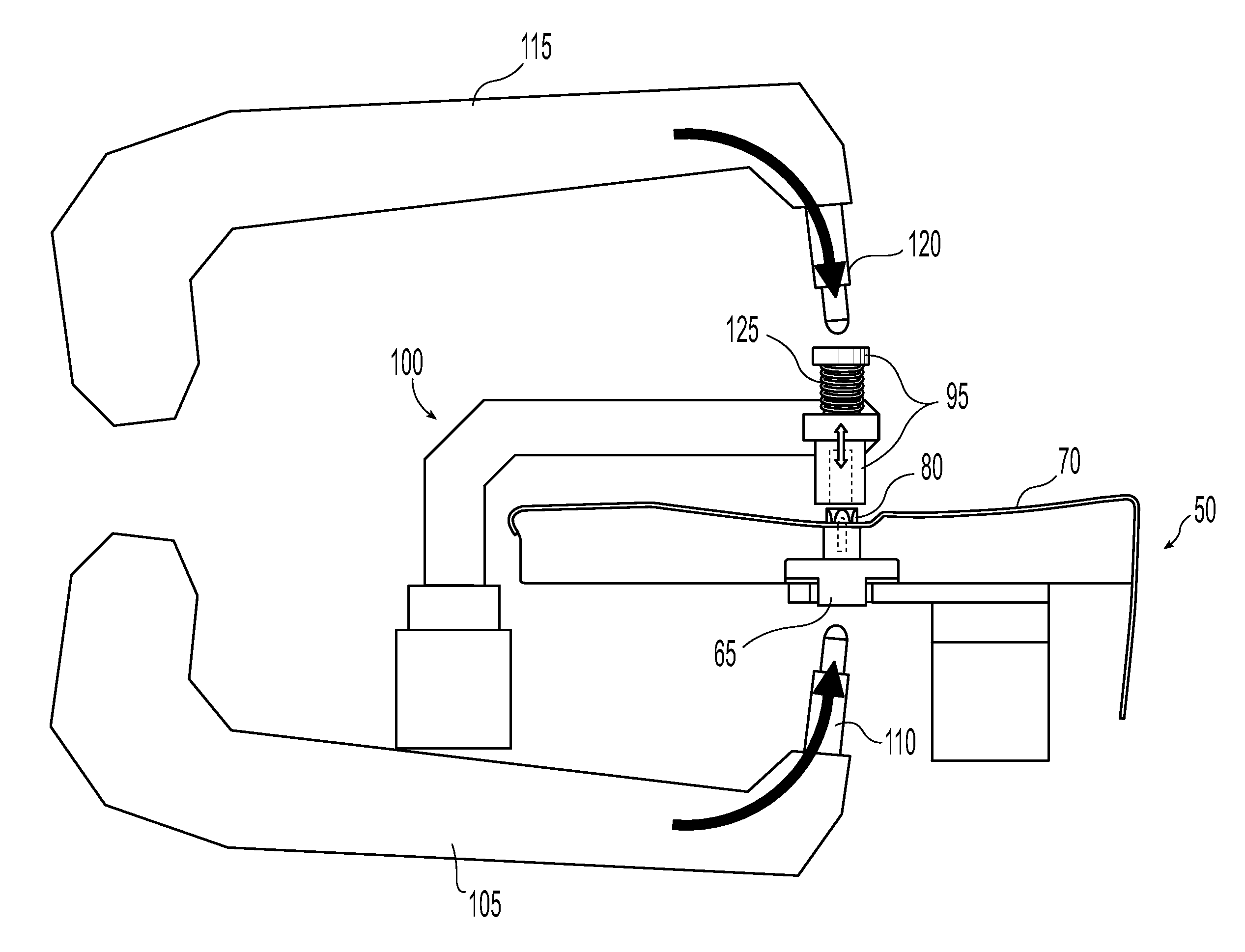
[0006]The present invention generally comprises a robotic resistance welding robot in combination with a work piece fixture for supporting a work piece, and one or more pairs of contacting electrodes for transferring electric current from the welding robot to the projection nut(s) and work piece. The present invention allows for the elimination of, or a reduction in, work piece handling on the part of an operator. The system and process of the present invention also permits the welding of projection weld nuts to a wide variety of work pieces without the need to design and construct complex dedicated welding devices. Rather, a single welding robot in combination with one or more simple fixtures can be used to accomplish the welding of projection weld nuts to a wide variety of work pieces.
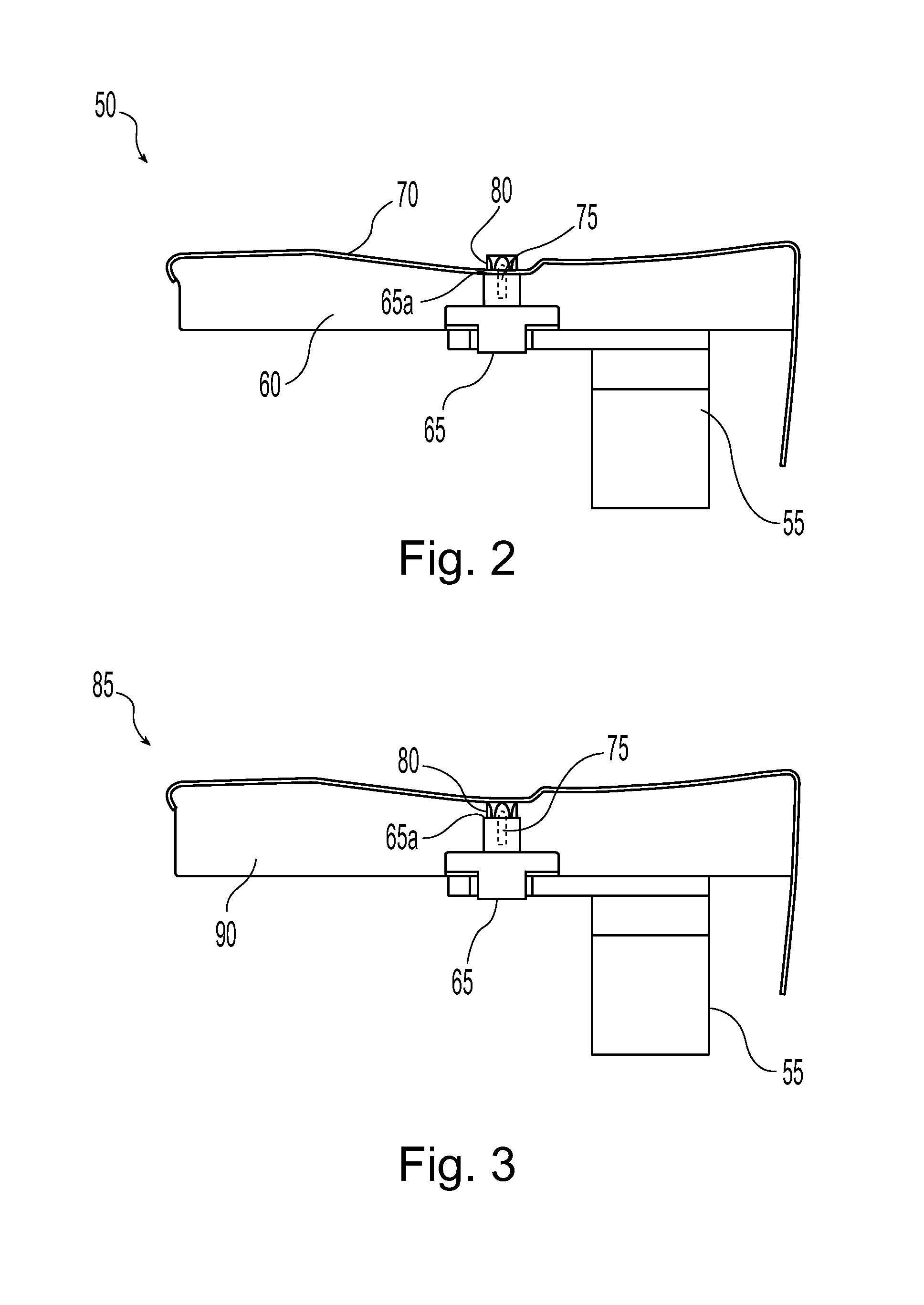
[0008]The work piece fixture may include a support bracket or other support structure that also houses a first contacting electrode. The first contacting electrode is adapted for contact by a first weld electrode of the welding robot, and to transfer current therefrom to the work piece and projection weld nut. The first contacting electrode may be of various designs, but preferably contacts a surface of the work piece in the area of the projection weld nut. The first contacting electrode may also include one or more elements to help fix the position of a projection weld nut.

Problems solved by technology

The problem with such a system is that it requires specialized equipment unique to the work piece at issue, and also commonly necessitates much handling by an operator.

Method used


Image

  • Robotic welding system and method for welding projection weld nuts
  • Robotic welding system and method for welding projection weld nuts
  • Robotic welding system and method for welding projection weld nuts

Examples


Embodiment Construction

)

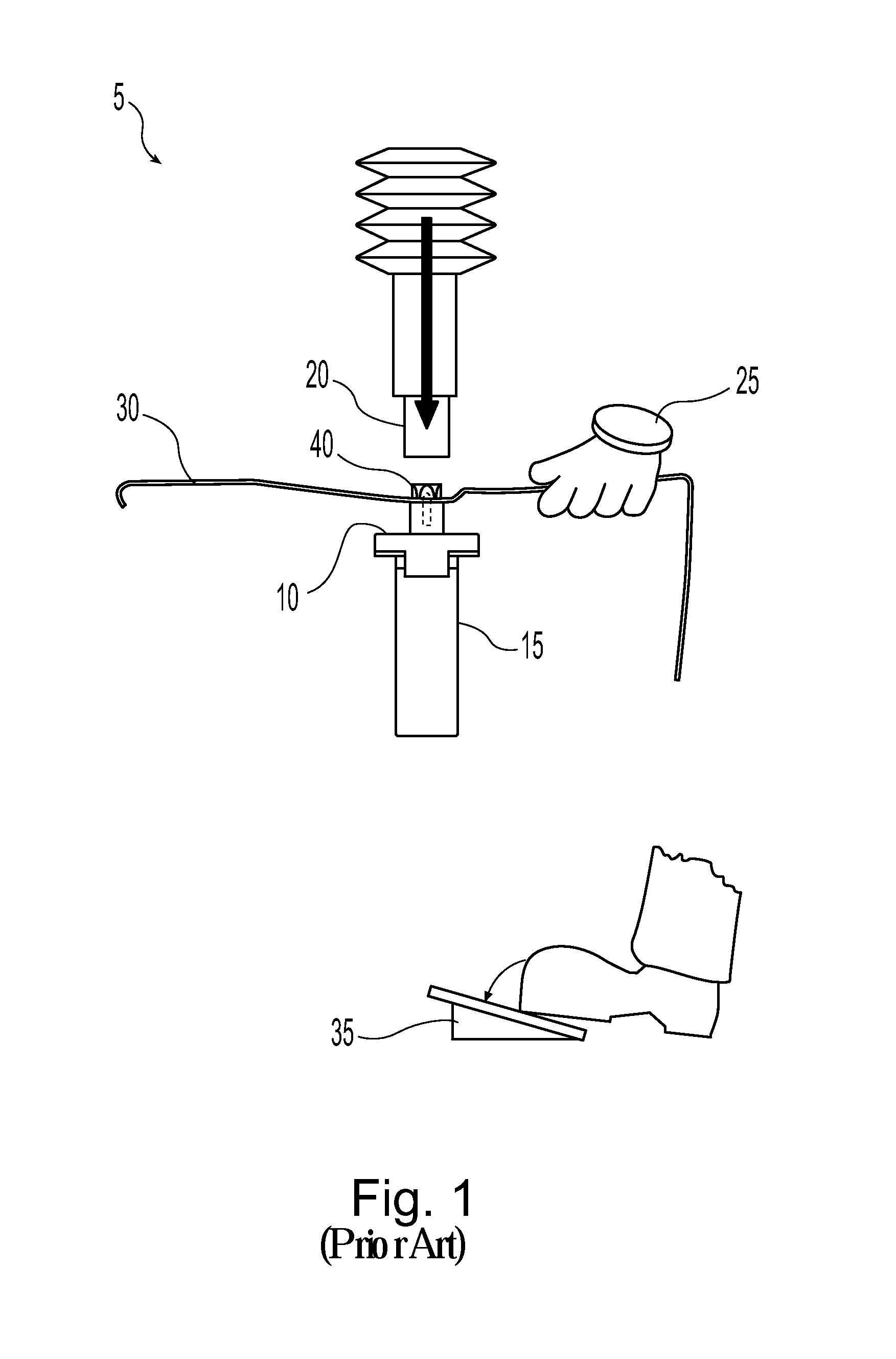
[0022]As can be understood from a review of FIG. 1, known systems for welding projection weld nuts typically require considerable interaction by an operator, as well as dedicated equipment designed for a particular application. As shown, this known welding system 5 includes a fixed lower electrode 10 and support 15, and a vertically displaceable upper electrode 20. Generally, these components will be a part of a specialized resistance welding apparatus. Such an apparatus is generally designed for use specifically with a particular work piece. Consequently, such an apparatus often cannot be adapted, at least not economically, for use with a different work piece.

[0023]As can also be observed in FIG. 1, an operator 25 is often required to hold or otherwise manually support a work piece 30 in a proper welding position. With the work piece held in proper position, the operator 25 then typically initiates the welding process, such as by depressing a footswitch 35 or by activating some ot...


PUM

PropertyMeasurementUnit
electric currentaaaaaaaaaa
pressureaaaaaaaaaa
meltingaaaaaaaaaa

Abstract

A system and method for welding projection weld nuts to a work piece. The system and method of the present invention generally makes use of a fixtured work piece having one or more projection weld nuts associated therewith. A resistance welding robot is used to weld the projection weld nuts to the work piece. The welding robot typically has weld electrodes therewith, through which electric welding current is passed to the projection weld nut(s) and the work piece. A first and second contacting electrode is used to transfer electric current from the welding robot electrodes to the projection weld nut(s) and work piece.

Description

BACKGROUND OF THE INVENTION[0001]The present invention is directed to an improved system and method for welding projection weld nuts. More particularly, the present invention is directed to a robotic system and method for welding projection weld nuts.[0002]Projection weld nuts would be well known to one skilled in the art. However, in brief, projection weld nuts are generally threaded nuts designed especially for attachment to a metallic work piece via resistance welding. To facilitate welded attachment, projection weld nuts include several portions of weld material that project outward from a welding face (i.e., the face of the projection weld nut that will contact the work piece). The projection weld nut is placed into contact with a work piece, typically in or over a pilot hole, pressure is preferably applied, and a resistance welding apparatus is used to pass current through the work piece and the projection weld nut. The current causes a melting of the weld material projections...

Claims


Application Information

Patent Timeline
Patent Type & Authority Patents(United States)
IPC IPC(8): B23K11/14
CPCB23K11/0046B23K11/314B23K11/36
Inventor TSUCHIYA, HIROKITAKAHASHI, NOBORU
Owner HONDA MOTOR CO LTD
Learn More