Fault management system for a communications network

a communication network and fault management technology, applied in the direction of error detection/correction, supervisory/monitoring/testing arrangements, instruments, etc., can solve problems such as physical damage to a node, user suffering a loss of service, and prone faults in terminal circuits

Active Publication Date: 2007-07-31
BRITISH TELECOMM PLC
View PDF20 Cites 19 Cited by
  • Summary
  • Abstract
  • Description
  • Claims
  • Application Information

AI Technical Summary

Benefits of technology

[0016]By providing an indication of the relative cost of repair of a circuit or network element, the resources that are likely to be required to meet the repair can be put in pl

Problems solved by technology

Unfortunately, terminating circuits are prone to faults.
In the case of a conventional access network formed from pairs of wires, the causes of the faults include ingress of water into a node and also physical damage to a node.
However, until the fault is repaired, the user suffers a loss of service.
Such routine tests can detect a fault on a terminating circuit.
Where the operat

Method used


Image

  • Fault management system for a communications network
  • Fault management system for a communications network
  • Fault management system for a communications network

Examples


Embodiment Construction

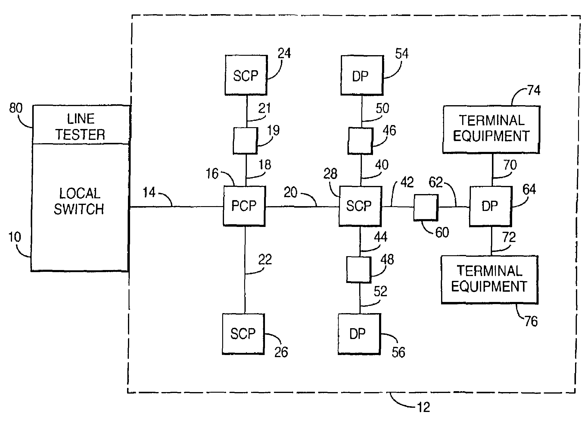
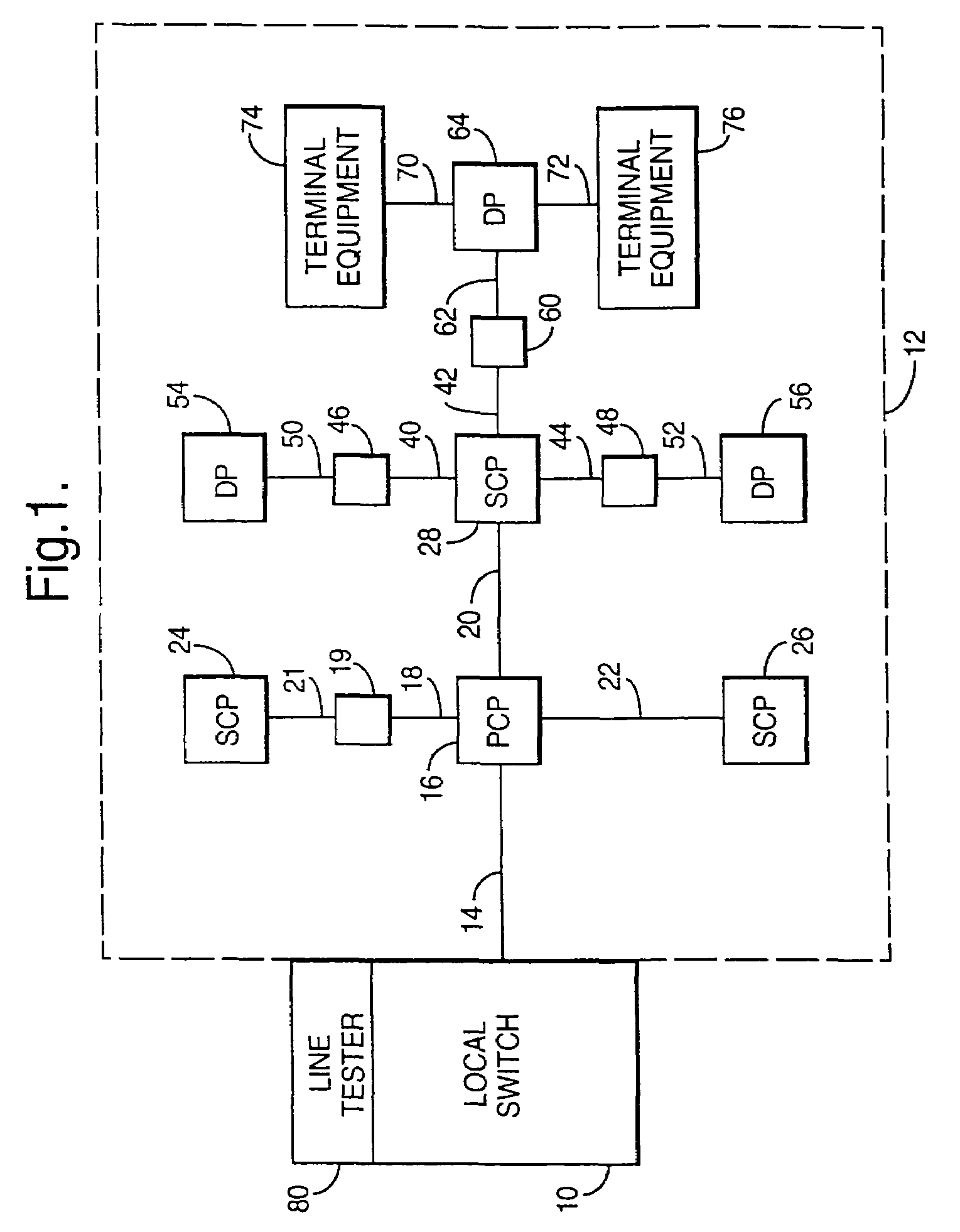
[0033]Referring now to FIG. 1, there is shown a local switch 10 and a conventional access network 12 connected to the local switch 10. The local switch 10 and the access network 12 form part of a communications network. The local switch 10 is connected to the terminating circuits or lines of the access network 12. Typically, a local switch is connected to several thousand terminating circuits. Each terminating circuit or line passes through several nodes before reaching its respective terminal equipment. These nodes comprise primary cross-connect points, secondary cross-connect points, distribution points (DPs) and junctions and examples of these nodes will be described below.

[0034]In the conventional access network 12 shown in FIG. 1, each terminating circuit or line is formed from a pair of copper wires. The copper wires leave the local switch 10 in the form of one or more cables. One of these cables is shown in FIG. 1 and indicated by reference numeral 14. The far end of cable 14...


PUM


Abstract

A fault management system is directed to the access network part of a communications network where terminating lines in the form of pairs of copper wires extend from a local switch through a series of nodes to terminal equipment provided for user of the network. Each night, a test head performs a series of tests on each of the terminating lines. The results of the tests are transmitted to an access network management system where they are analyzed with respect to a set of parameters to identify characteristics that would indicate that a fault is likely to occur on the associated circuit within a predetermined period e.g. 1 year. Further analysis can then be carried out to establish the probability of the fault actually occurring and/or whether the potential fault analyzed is going to occur in either the underground or the over-ground part of the network. Further analysis determines relative costs of repair for circuits or network elements in which faults or potential faults have been identified.

Description

[0001]This application is the US national phase of international application PCT / GB01 / 05555 filed 17 Dec. 2001 which designated the U.S.BACKGROUND[0002]1. Technical Field[0003]This invention relates to a fault management system for managing faults in the terminating circuits of a communications network and also to a method of operating such a fault management system.[0004]2. Related Art[0005]A conventional communications network comprises a relatively small number of interconnected main switches and a much larger number of local switches, each of which is connected to one or two main switches. The local switches are connected to the terminating circuits of the network and the far ends of these circuits are connected to terminal equipment such as telephone instruments provided for users of the network. The network formed from the main switches and local switches is known as the core network while a network formed from the terminating circuits is known variously as an access network o...

Claims


Application Information

Patent Timeline
IPC IPC(8): G06F11/00H04M3/30
CPCH04M3/30H04M3/305H04M2201/18
Inventor MAXWELL, RICHARD
Owner BRITISH TELECOMM PLC
Why Eureka
Try Eureka