Double locking handcuffs

a double-locking, handcuff technology, applied in the field of manacles and cuffs, can solve the problem that the camera is somewhat more difficult to move in the actuation direction, and achieve the effect of preventing the camera from disengaging

Active Publication Date: 2007-08-07
SMITH & WESSON INC
View PDF16 Cites 12 Cited by
  • Summary
  • Abstract
  • Description
  • Claims
  • Application Information

AI Technical Summary

Benefits of technology

[0009]An embodiment of a double locking handcuff according to the present invention includes a jaw operably connected to a housing (e.g., a front cheek, a frame, and a rear cheek, all respectively stacked atop and connected to one another). The jaw cooperates with a bolt that is pivotally disposed in an interior of the housing. The bolt is biased downwards against the jaw by a bolt spring positioned in the interior space of the housing. The bolt spring can be laterally shifted between a first, “single-lock” position, and a second, “double-lock” position. In the former, the bolt can be disengaged from the jaw upon the application of a force overcoming the biasing effect of the spring. In the latter, the bolt is prevented from disengaging from the jaw, preventing someone from thwarting the cuff by manipulating the bolt. The handcuff further includes a cam pivotally disposed within a slot extending through the housing. The cam is accessible and moveable by hand from the exterior of the housing for laterally shifting or otherwise moving the spring from the single-lock position to the double-lock position.
[0011]Because the cam is movable using a single thumb or finger, and without the need for the handcuff key or for finding a double lock slot or pinhole, the double lock mechanism can be easily and quickly actuated by a law enforcement officer or other user even in low-light situations, as well as in situations where two hands are not available or when a suspect is moving or otherwise resisting. Also, the resistance of the spring to movement inside the frame interior space is felt by the user during actuation of the cam, thereby providing positive tactile feedback to the user as to whether or not the handcuff has been double locked: when the handcuff is double locked the cam can be freely pivoted back and forth, and when the handcuff is not double locked the cam is somewhat more difficult to move in its actuation direction.

Problems solved by technology

Also, the resistance of the spring to movement inside the frame interior space is felt by the user during actuation of the cam, thereby providing positive tactile feedback to the user as to whether or not the handcuff has been double locked: when the handcuff is double locked the cam can be freely pivoted back and forth, and when the handcuff is not double locked the cam is somewhat more difficult to move in its actuation direction.

Method used


Image

  • Double locking handcuffs
  • Double locking handcuffs
  • Double locking handcuffs

Examples


Embodiment Construction

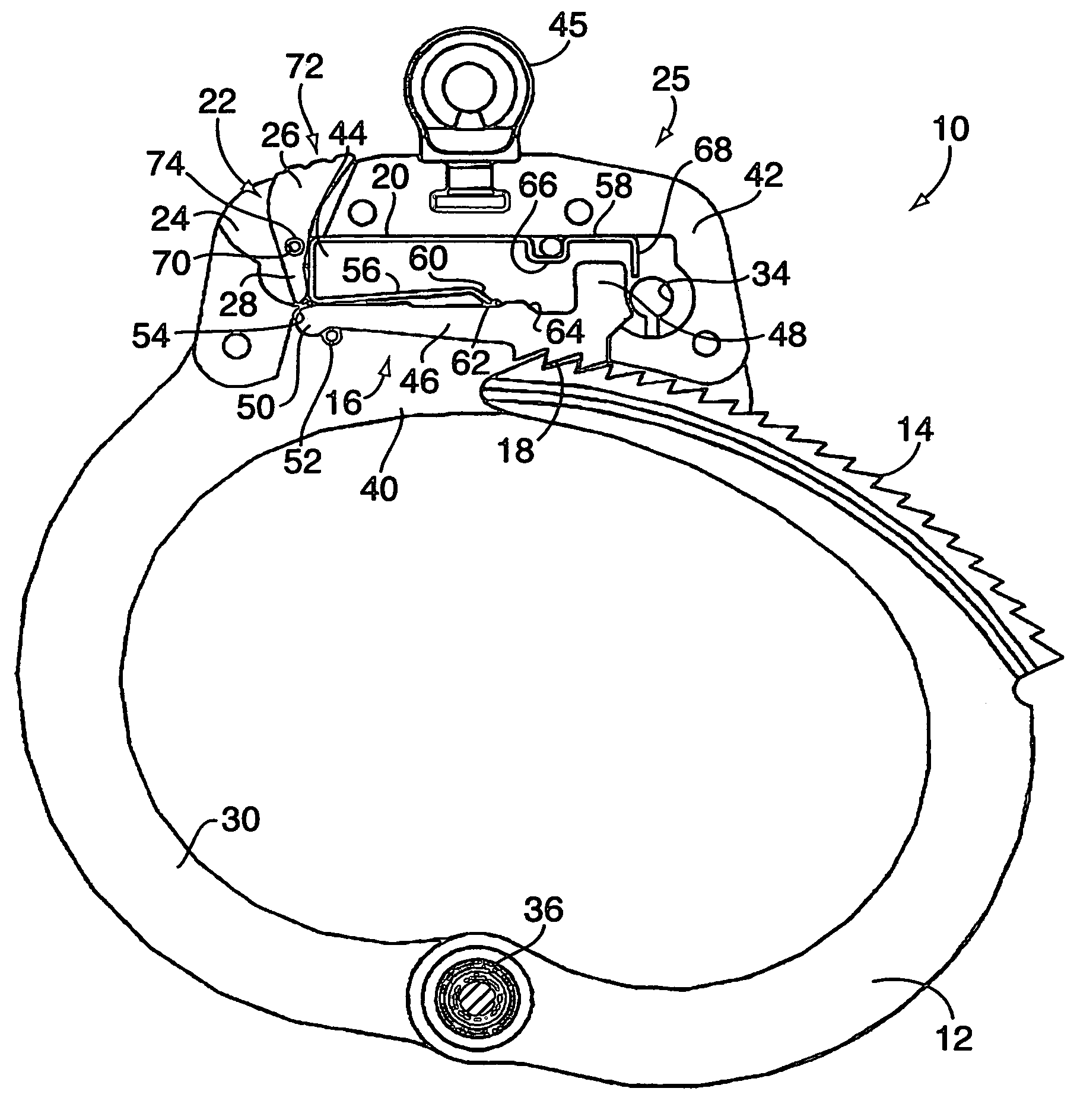
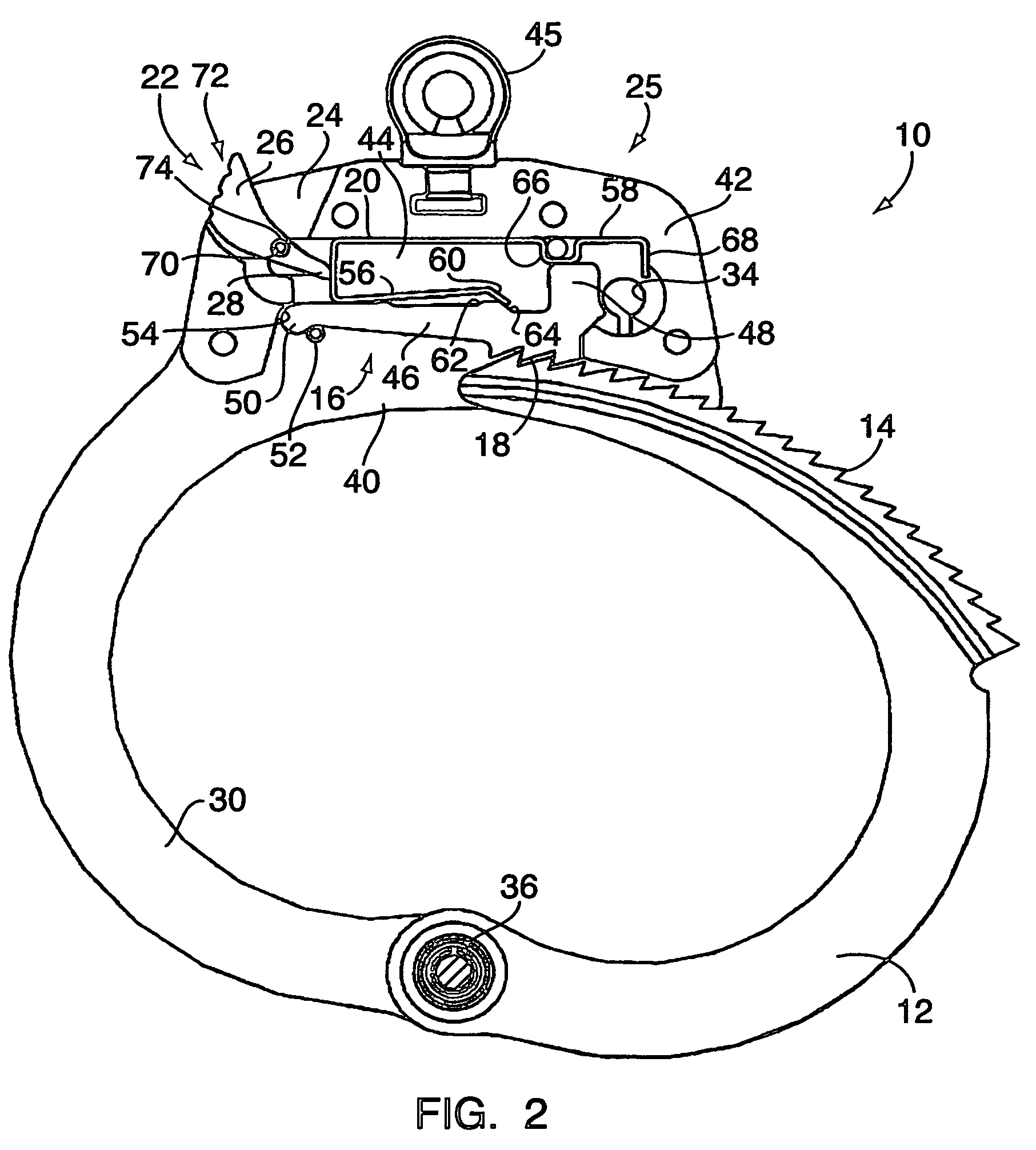
[0025]With reference to FIGS. 1–6, an embodiment of a handcuff 10 with double lock mechanism comprises a pivoting jaw 12 with ratchet-like teeth 14 that cooperates with a pivoting bolt 16. The bolt 16 has reverse-facing teeth 18, and is biased downwards against the jaw 12 by a bolt spring 20. The spring 20 is laterally moveable between a first, “single-lock” position, as shown in FIG. 1, and a second, “double-lock” position, as shown in FIG. 2. For double locking the handcuff 10, a hand-operated, pivoting cam member 22 is provided. (By “hand-operated,” it is meant that the cam can be directly actuated using a finger or thumb.) The cam 22 is disposed within a slot 24 extending through a cuff housing 25. A wide, upper end 26 of the cam 22 is accessible from the top of the cuff, and a narrower, depending leg portion 28 of the cam 22 is positioned against the spring 20. To laterally shift the spring 20 from its single-lock position to its double-lock position, the cam upper end 26 is mo...


PUM


Abstract

A double locking handcuff includes an interior spring laterally moveable between single- and double-lock positions. A finger-operated, pivoting cam is disposed within a slot extending through the cuff frame, and has a wide upper end accessible from the top of the cuff and a narrow, leg-like lower end positioned for movement against the spring. For double locking the handcuff, the cam upper end is moved downwards by hand. This causes the cam leg to press against and laterally shift the spring to its double-lock position. Because the cam is movable by hand and without the need for the handcuff key or for finding a double lock slot or pinhole, the double lock mechanism can be easily and quickly actuated. Also, when the handcuff is double locked the cam can be freely pivoted back and forth, providing direct tactile feedback that the handcuff is double locked.

Description

[0001]This application claims the benefit of U.S. Provisional Application Ser. No. 60 / 638,209 filed Dec. 21, 2004, hereby incorporated by reference in its entirety.TECHNICAL FIELD[0002]The present invention relates to portable locks and, more particularly, to manacles and cuffs.BACKGROUND OF THE INVENTION[0003]Manacles, shackles, and handcuffs are portable locking devices used, e.g., by law enforcement personnel, to temporarily but securely bind or restrain suspects and other persons in custody. The basic modern handcuff design has proven very successful both in terms of functionality and low manufacturing costs, and has changed little over the years.[0004]One typical design for double locking handcuffs is shown in U.S. Pat. No. 4,287,731. In the '731 patent, in a central cavity in the handcuff frame, a laterally-moveable spring element biases a pivoting bolt in a downwards direction against the cuff's pivoting jaw. The jaw and bolt have cooperating, oppositely facing ratchet teeth....

Claims


Application Information

Patent Timeline
Patent Type & Authority Patents(United States)
IPC IPC(8): E05B75/00
CPCE05B75/00Y10T70/404
Inventor WADE, TERRENCE L.
Owner SMITH & WESSON INC
Why Eureka
Try Eureka