Photoluminescent tube system

a technology of photoluminescent tubes and signaling systems, applied in the direction of lighting applications, landing aids, and luminescence, can solve the problems of room for judgment errors and expired flashlight batteries

Inactive Publication Date: 2007-08-07
PLASZCZ STEVE F
View PDF20 Cites 14 Cited by
  • Summary
  • Abstract
  • Description
  • Claims
  • Application Information

AI Technical Summary

Problems solved by technology

At times, the wingwalkers are unable to locate the flashlights from the previous shift or the batteries of the flashlights expire.
In inclement weather, the crew must decide which signaling wand is best suited for the conditions, which also leaves room for judgment error.

Method used


Image

  • Photoluminescent tube system
  • Photoluminescent tube system
  • Photoluminescent tube system

Examples


Embodiment Construction

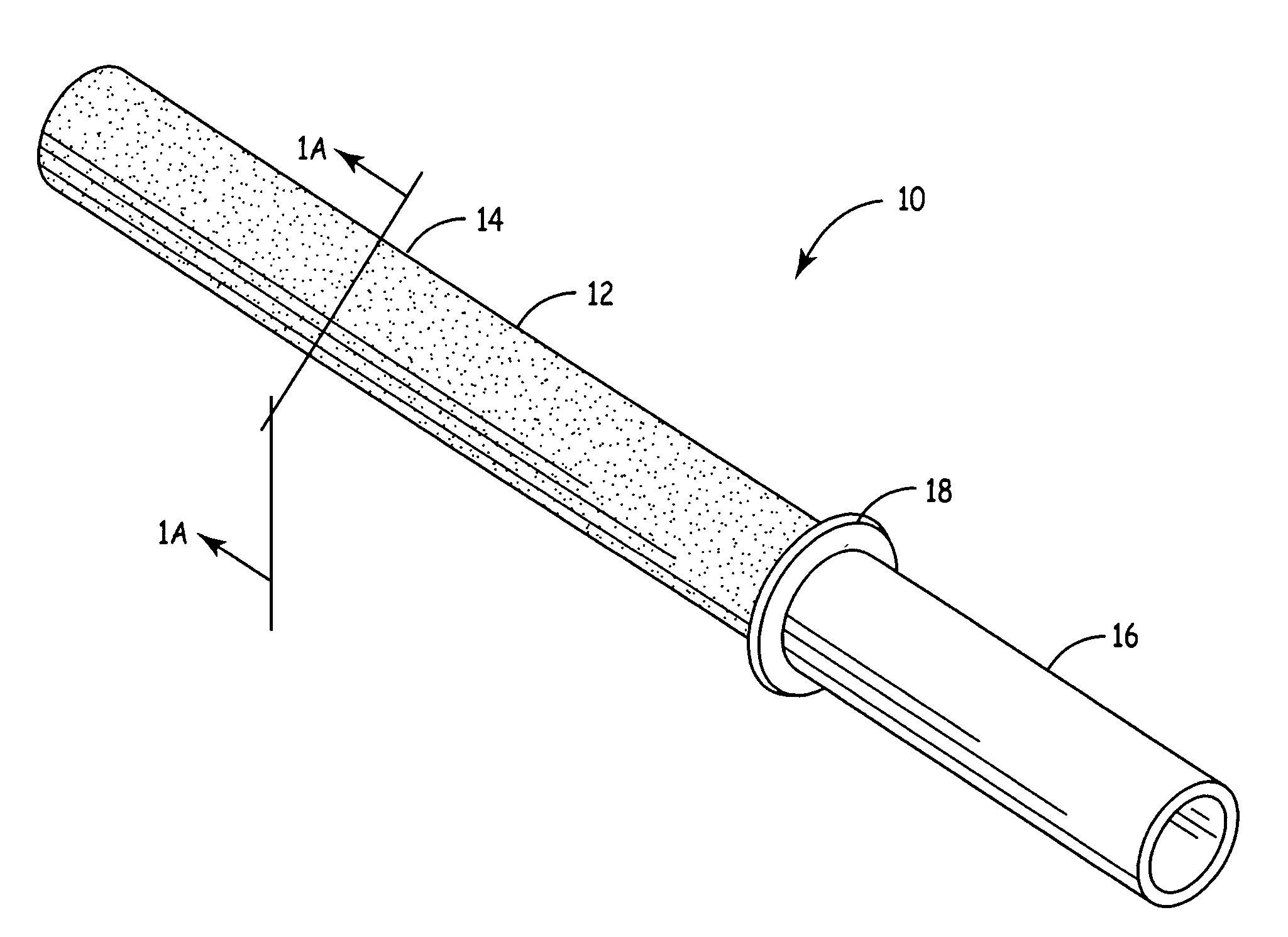
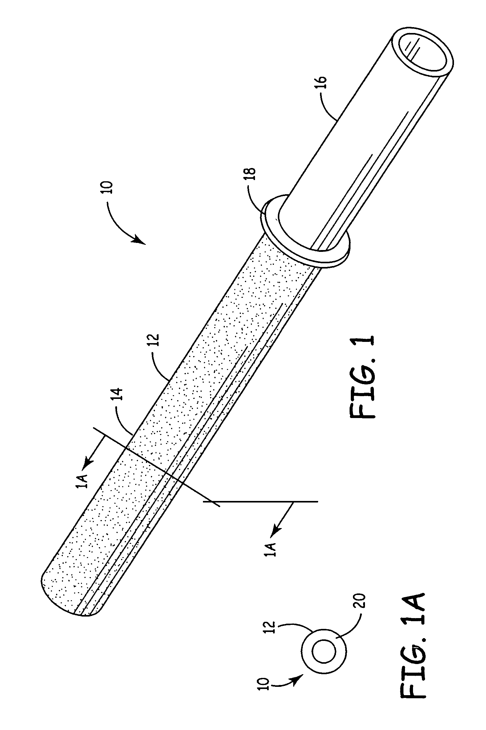
[0019]The present invention comprises an easily constructed, low cost photoluminescent signal wand that functions in both daylight and night / low light-conditions. FIG. 1 is a perspective view of a first embodiment of signaling wand of the present invention. Signaling wand 10 is comprised of an elongate tubular body 12 having a signaling portion 14, a handle portion 16 and a collar 18 therebetween which surrounds the tubular body 12. In one embodiment, tubular body 12 is formed by molding or extruding a mixture consisting of a translucent thermoset resin, a high visibility pigment and a light activated phosphorescent powder, of which the phosphorescent powder is approximately thirty percent by volume. The mixture is mixed to equally disperse the pigment and phosphorescent powder in the resin and a hardener is added to cure the mixture to maintain the dispersion of the pigment and phosphorescent powder. After these materials are mixed they may be extruded or molded to form a tube, as ...


PUM


Abstract

A plurality of signal wands having a handle and a signaling portion comprising photoluminescent material and a high visibility pigment are stored in a lighted receptacle for use in either high light or low light conditions. Openings provided in one wall of the receptacle permit the signaling portion of each signal wand to be inserted into an internal chamber of the receptacle, which houses a plurality of full spectrum light bulbs. The signal wands and light bulbs are oriented relative to one another in a pattern that ensures that the signaling portions are substantially surrounded by light. Exposed to light for as little as five minutes, the signaling portion of the signal wands glow with sufficient intensity and for a sufficient duration to signal vehicles, such as aircraft operating near airport gates, in low light conditions. The high visibility pigment associated with the signaling portion enables the signal wands also to be used for daytime signaling.

Description

CROSS-REFERENCE TO RELATED APPLICATION(S)[0001]None.BACKGROUND OF THE INVENTION[0002]This invention relates to a signaling system. More specifically, this invention relates to a photoluminescent signaling system for guiding vehicles, such as aircraft, in both low and high light conditions.[0003]Commercial aircraft requires a ground based signaling system to guide aircraft towards and away from airport gates. A ground crew of five individuals, including a supervisor, a marshaller, a driver of a pushout tractor and two wingwalkers, is used to safely guide aircraft. The marshaller stands on the ground at the front of the plane and has contact with the pilot via a headset. The driver of the pushout tractor uses the pushout tractor to push the plane into place. The wingwalkers stand on the ground on opposite sides of the plane towards the rear. The wingwalkers are responsible for escorting the aircraft away from the gate to a ramp where the aircraft is released for taxiing. The wingwalke...

Claims


Application Information

Patent Timeline
Patent Type & Authority Patents(United States)
IPC IPC(8): F21V9/16
CPCB64F1/20F21V9/16F21W2111/06F21V9/02F21V13/08F21V9/30
Inventor PLASZCZ, STEVE F.
Owner PLASZCZ STEVE F
Why Eureka
Try Eureka