System and method for stimulus calibration for an implantable pulse generator

Active Publication Date: 2007-08-07
ADVANCED NEUROMODULATION SYST INC
View PDF2 Cites 113 Cited by
  • Summary
  • Abstract
  • Description
  • Claims
  • Application Information

AI Technical Summary

Problems solved by technology

Unfortunately, this process is generally inconvenient and time consuming for both the patient and the profess

Method used


Image

  • System and method for stimulus calibration for an implantable pulse generator
  • System and method for stimulus calibration for an implantable pulse generator
  • System and method for stimulus calibration for an implantable pulse generator

Examples


Embodiment Construction

[0022]FIGS. 1 through 5, discussed below, and the various embodiments used to describe the principles of the present invention in this patent document are by way of illustration only and should not be construed in any way to limit the scope of the invention. Those skilled in the art will understand that the principles of the present invention may be implemented in any suitably arranged device. The numerous innovative teachings of the present application will be described with particular reference to the presently preferred embodiment.

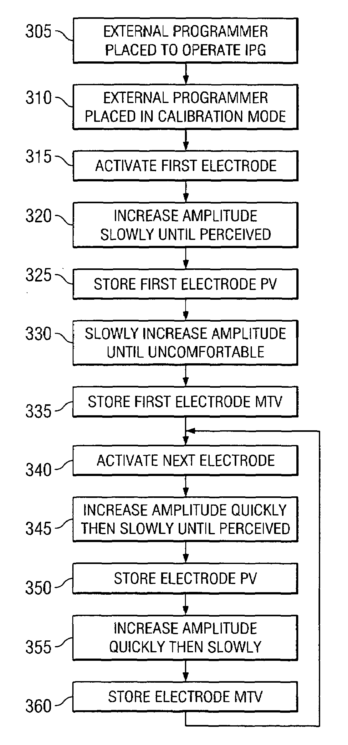
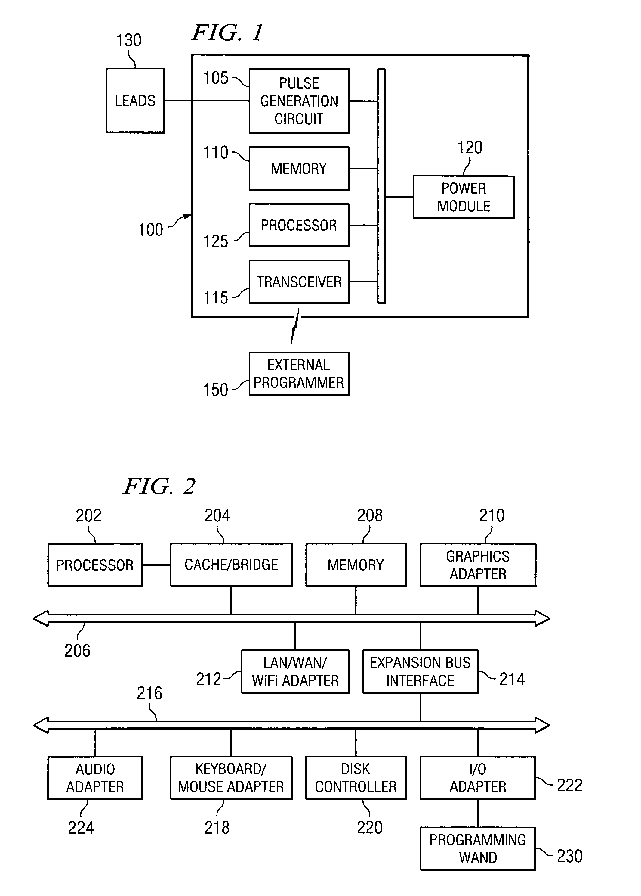
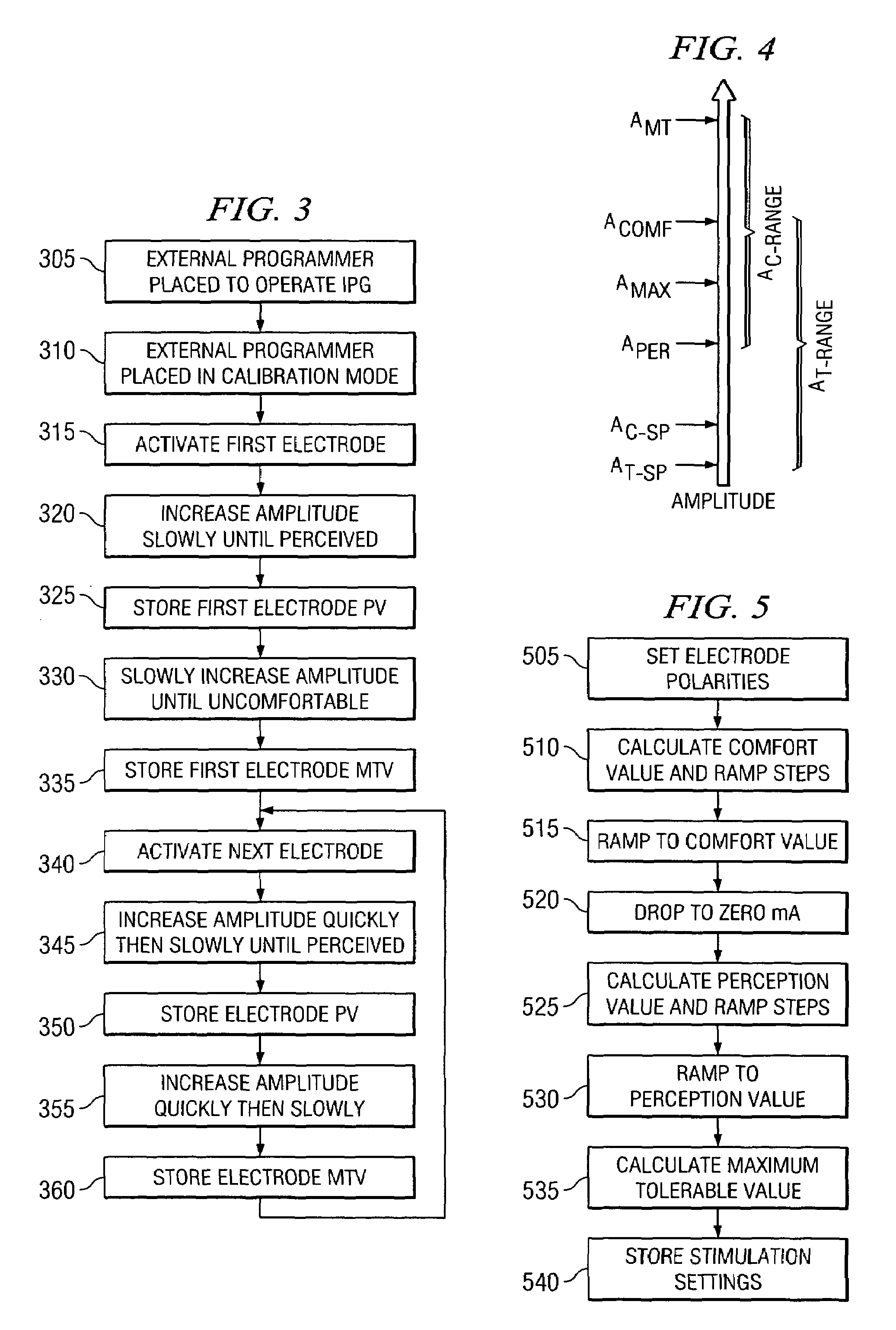
[0023]In embodiments of the present invention, there are an apparatus and methods for calibrating and / or testing a stimulation device such as, for example, an implantable pulse generator (IPG). The PG, whether it is a self-contained implantable pulse generator (SCIPG) or externally-powered implantable pulse generator (EPIPG), communicates with an external programmer to determine the characteristics of the stimuli delivered to the lead electrodes. An ext...


PUM


Abstract

A system, method, and computer program product for calibrating a stimulation device such as an implantable pulse generator (IPG). An IPG, whether it is a self-contained implantable pulse generator (SCIPG) or externally-powered implantable pulse generator (EPIPG), communicates with an external programmer to determine the characteristics of the stimuli delivered to the lead electrodes. An external programmer is used with patient feedback to determine initial threshold levels, and using the initial threshold levels, to determine threshold levels for combined electrode arrays.

Description

CROSS-REFERENCE TO RELATED APPLICATIONS[0001]This application claims priority benefit of U.S. Provisional Patent Application No. 60 / 550,040 entitled “SYSTEM AND METHOD FOR STIMULUS CALIBRATION FOR AN IMPLANTABLE PULSE GENERATOR,” filed Mar. 4, 2004, the disclosure of which is hereby incorporated herein by reference. This application is related to concurrently filed “SYSTEM AND METHOD FOR GENERATING AND TESTING TREATMENT PROTOCOLS”, application Ser. No. 11 / 072,998, the disclosure of which is hereby incorporated herein by reference.TECHNICAL FIELD OF THE INVENTION[0002]The present invention is directed, in general, to medical devices and more specifically to neurostimulation devices.BACKGROUND OF THE INVENTION[0003]The present invention relates to stimulation systems, for example, spinal cord, peripheral, and deep-brain stimulation systems. A spinal cord stimulation system is an implantable pulse generating system used to provide electrical stimulation pulses from an electrode array p...

Claims


Application Information

Patent Timeline
IPC IPC(8): A61N1/00A61B5/05
CPCA61N1/08A61N1/36071A61N1/3787A61N1/36185A61N1/37235
Inventor ERICKSON, JOHN H.HICKMAN, THOMAS K.ENGSTROM, ERIK D.
Owner ADVANCED NEUROMODULATION SYST INC
Why Eureka
Try Eureka