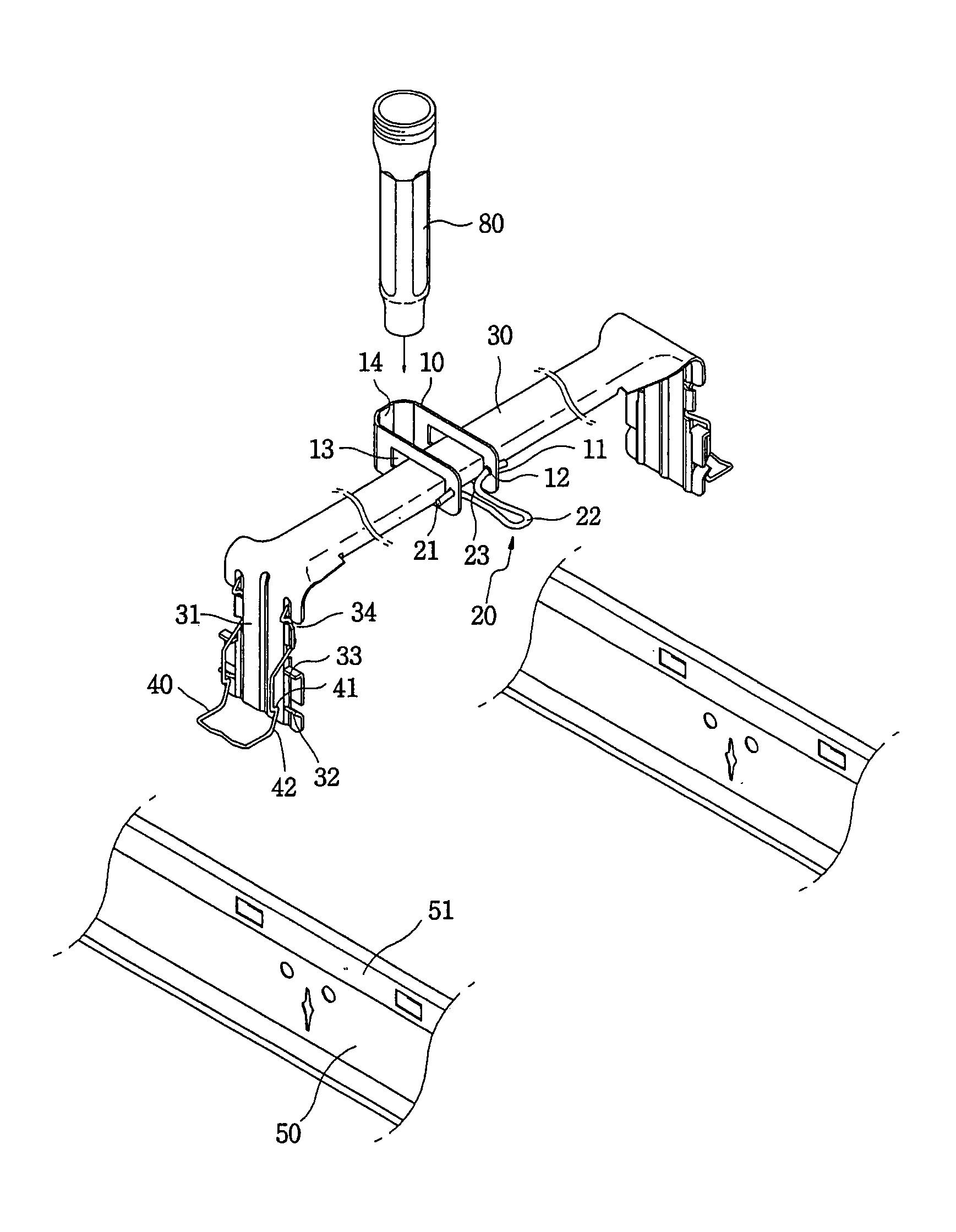
Mounting structure for sprinklers

a technology for mounting structures and sprinklers, which is applied in the direction of filing appliances, machine supports, and suspension devices of curtain suspension devices, etc., can solve the problem of inefficiency of the conventional sprinkler mounting process

Active Publication Date: 2007-08-14
KOFULSO
View PDF23 Cites 67 Cited by
  • Summary
  • Abstract
  • Description
  • Claims
  • Application Information

AI Technical Summary

Benefits of technology

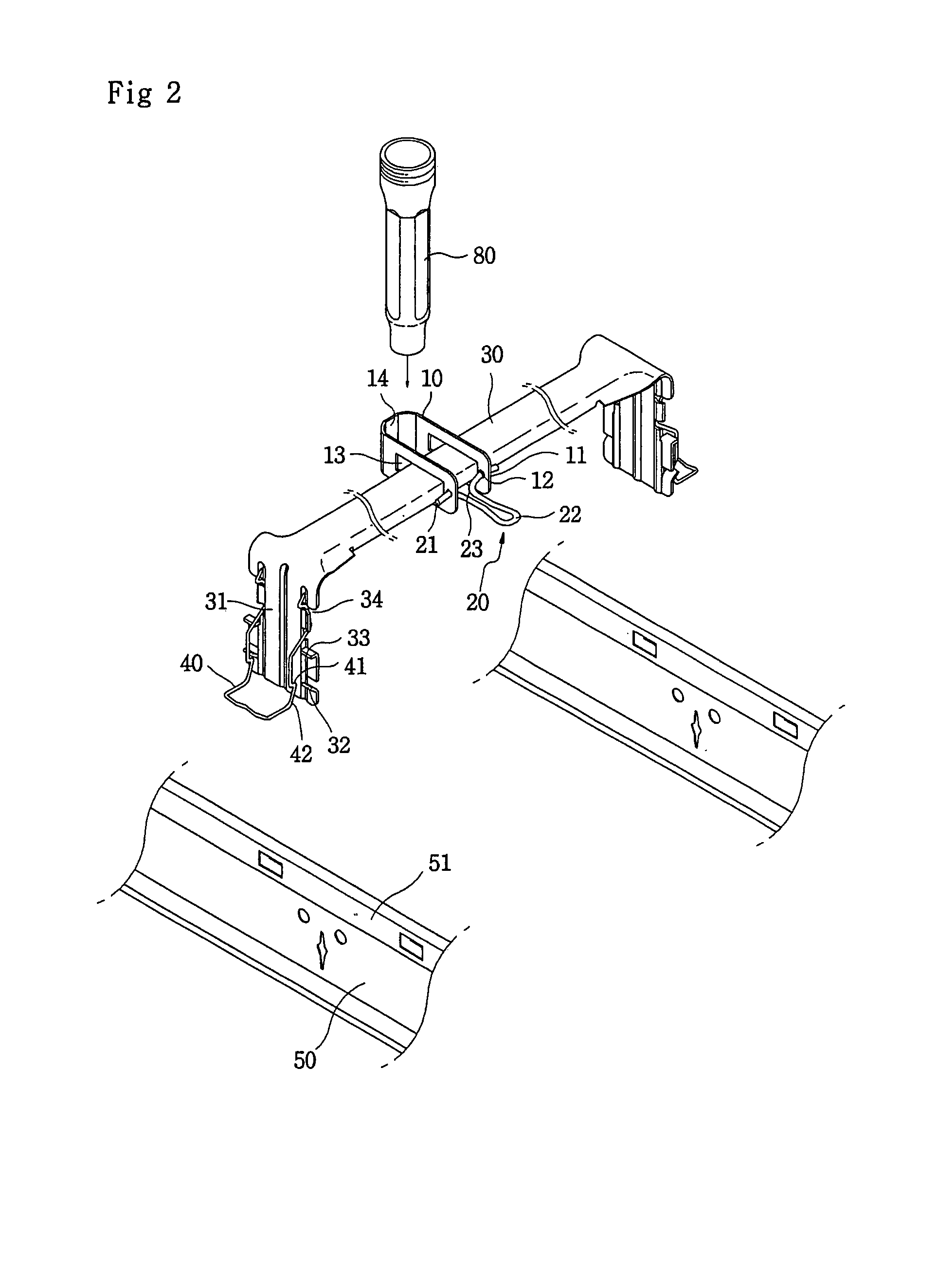
[0007]Accordingly, the present invention has been made keeping in mind the above problems occurring in the prior art, and an object of the present invention is to provide a mounting structure for sprinklers in which a latitudinal support unit includes elastic units at opposite ends thereof, so that the latitudinal support unit can be easily mounted to a longitudinal support unit merely by pushing the latitudinal support unit downwards onto the longitudinal support unit.
[0008]Another object of the present invention is to provide a mounting structure for sprinklers which is capable of reliably fastening a sprinkler reducer to a mounting bracket, mounted to the latitudinal support unit, simply by rotating a locking unit on the mounting bracket in a predetermined direction.
[0009]A further object of the present invention is to provide a mounting structure for sprinklers which is able to easily mounting the sprinkler reducer to the latitudinal support unit after coupling the sprinkler reducer to both a fire water pipe and a sprinkler head.

Problems solved by technology

Therefore, the conventional sprinkler mounting process is inefficient, compared with a sprinkler mounting process in which a sprinkler reducer is mounted to a latitudinal support unit after a sprinkler head is coupled to the sprinkler reducer.

Method used


Image

  • Mounting structure for sprinklers
  • Mounting structure for sprinklers
  • Mounting structure for sprinklers

Examples


first embodiment

[0042]FIGS. 13A through 13C are views showing holding parts 14 of mounting brackets 10 to more reliably couple the sprinkler reducer to the latitudinal support unit 30, according to modifications of the present invention. FIG. 13A shows a knurled portion provided in a holding part 14 of a mounting bracket 10. FIG. 13B shows a vertically elongated protrusion 14a provided in a holding part 14 of a mounting bracket 10. In the case of FIG. 13B, the sprinkler reducer 80 has a vertically elongated groove at a predetermined position to correspond to the vertically elongated protrusion 14a of the holding part 14. FIG. 13C shows a horizontally elongated protrusion 14b provided in a holding part 14 of a mounting bracket 10. In the case of FIG. 13C, the sprinkler reducer 80 has a horizontally elongated groove at a predetermined position to correspond to the horizontally elongated protrusion 14b of the holding part 14.

[0043]In the present invention having the above-mentioned structure, to coupl...

second embodiment

[0049]In the case of the second embodiment, the sprinkler reducer 80, which is coupled at an end thereof to a fire water pipe 90, is vertically placed at a predetermined position to be-in contact with a side of the latitudinal support unit 30.

[0050]In this state, to mount the mounting bracket 10A to the latitudinal support unit 30A, the latitudinal support unit 30A is horizontally inserted into the mounting space 13A of the mounting bracket 10A through the mouth 13C. At this time, the first end of the bracket arms, defining the mouth 13C and the mounting space 13A, is positioned outside the sprinkler reducer 80 (see, FIG. 8A).

[0051]Thereafter, the mounting bracket 10A, fitted over the latitudinal support unit 30, is rotated around the support part 13B so that the bracket arms surround the sprinkler reducer 80 and the other side of the sprinkler reducer 80 passes through the mouth 13C. Then, a holding part 14A of the mounting bracket 10A comes into close contact with an outer surface...


PUM


Abstract

Disclosed herein is a mounting structure for sprinklers. In the sprinkler mounting structure of the present invention, a latitudinal support unit has an elastic unit at each of opposite ends thereof, so that the latitudinal support unit can be reliably mounted to a pair of longitudinal support units merely by pushing the latitudinal support unit downwards on the longitudinal support unit. Furthermore, a mounting bracket, which is movably fitted over the latitudinal support unit to be adjusted in position, firmly holds a sprinkler reducer only by the rotation of a locking unit, coupled to the mounting bracket, in a predetermined direction.

Description

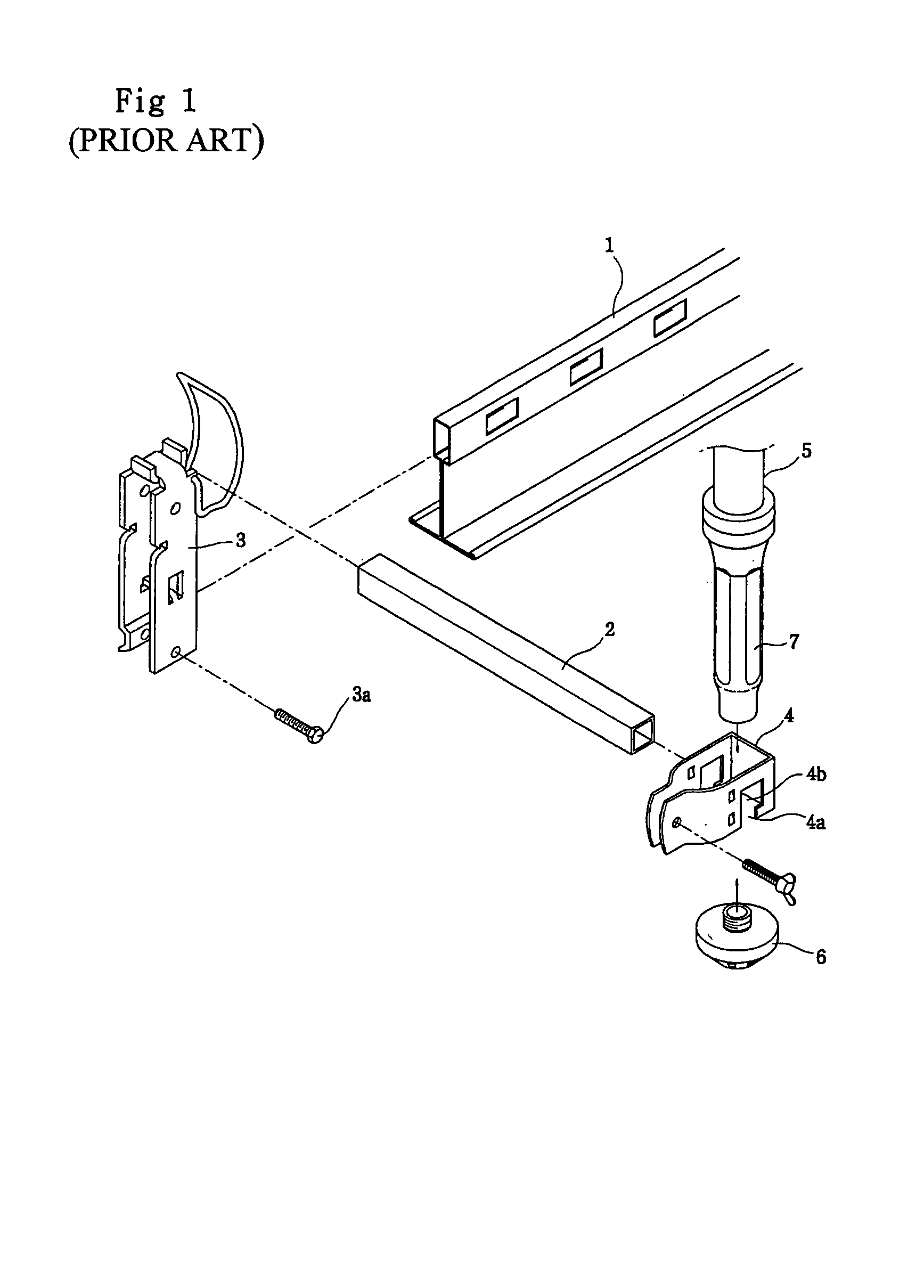
BACKGROUND OF THE INVENTION[0001]1. Field of the Invention[0002]The present invention relates generally to mounting structures for sprinklers and, more particularly, to a mounting structure for sprinklers by which a sprinkler reducer and a plurality of support units to support a sprinkler head are easily mounted at predetermined positions.[0003]2. Description of the Related Art[0004]Generally, a sprinkler reducer, to which a sprinkler head is coupled, is supported by a reducer mounting unit which is mounted to a latitudinal support unit that is provided on a ceiling plate in a building to arrange various wires on the ceiling plate. The latitudinal support unit is supported at opposite ends thereof by a longitudinal support unit.[0005]FIG. 1 is an exploded perspective view showing a conventional mounting structure for sprinklers. As shown in FIG. 1, the conventional sprinkler mounting structure includes a pair of longitudinal support units 1 which are mounted on the ceiling plate of ...

Claims


Application Information

Patent Timeline
Patent Type & Authority Patents(United States)
IPC IPC(8): E04B9/10F16L3/08
CPCA62C35/68E04B9/006F16L3/1058F16L3/24E04C2003/026F16L3/245F16L3/243A62C35/58
Inventor OH, SEUNG-IL
Owner KOFULSO
Why Eureka
Try Eureka