
Zone specific remote control panel for loading dock equipment

a technology for remote control and loading dock equipment, which is applied in the direction of electric controllers, ignition automatic control, instruments, etc., can solve the problems of inability of fork truck drivers to operate loading dock equipment, confusion in the proper sequence of operations, and untrained operators, so as to simplify the operating sequence, reduce the cost of installation, and compact space

Inactive Publication Date: 2007-08-14
4FRONT ENGINEERED SOLUTIONS
View PDF13 Cites 34 Cited by
  • Summary
  • Abstract
  • Description
  • Claims
  • Application Information

AI Technical Summary

Benefits of technology

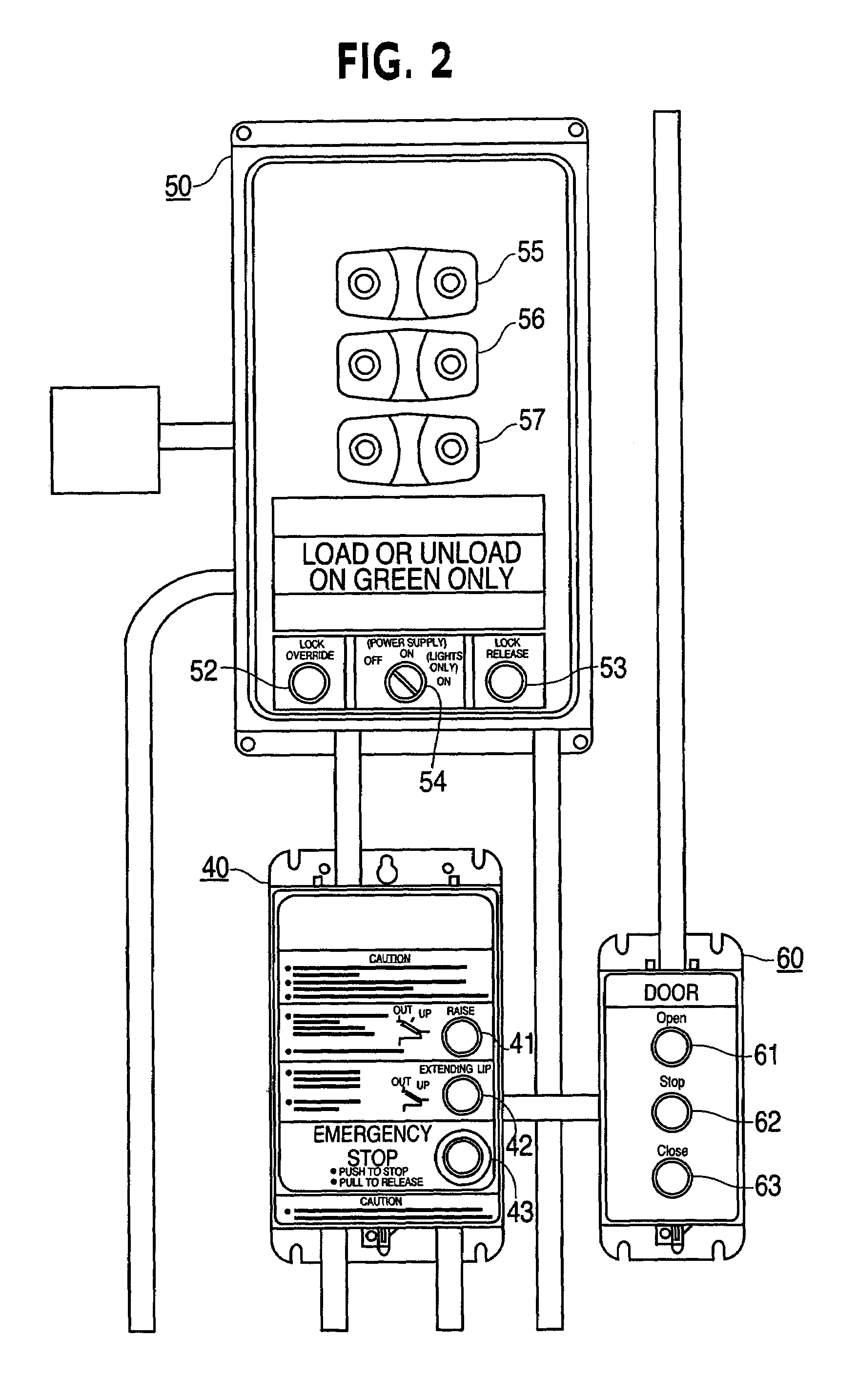
"The present invention provides a unified controller for a loading dock apparatus that combines the benefits of compact space and economical installation with a simplified operating sequence. The controller includes a control panel with operator controls for a vehicle restraint, a loading dock door, a dock leveler, and an emergency stop control. The control panel also includes indicator lights that indicate which control will activate, and a vehicle restraint bypass switch that can activate the vehicle restraint without engaging the dock apparatus. The invention allows for easy operation of the loading dock apparatus from within a fork truck and enables multiple dock bays to be operated with the same equipment but only one at a time."

Problems solved by technology

Although the control buttons and switches are arranged in functional groups and are clearly labeled, an untrained operator may find that the number of buttons and their differing locations make the proper sequence of operations seem confusing.
Another problem associated with loading and unloading of cargo at loading docks involves the inability of a fork truck driver from being able to operate the loading dock equipment while seated on the fork truck.
The constant getting in and out of the fork truck or the use of a second person to operate the loading dock equipment can be inefficient.

Method used


Image

  • Zone specific remote control panel for loading dock equipment
  • Zone specific remote control panel for loading dock equipment
  • Zone specific remote control panel for loading dock equipment

Examples


Embodiment Construction

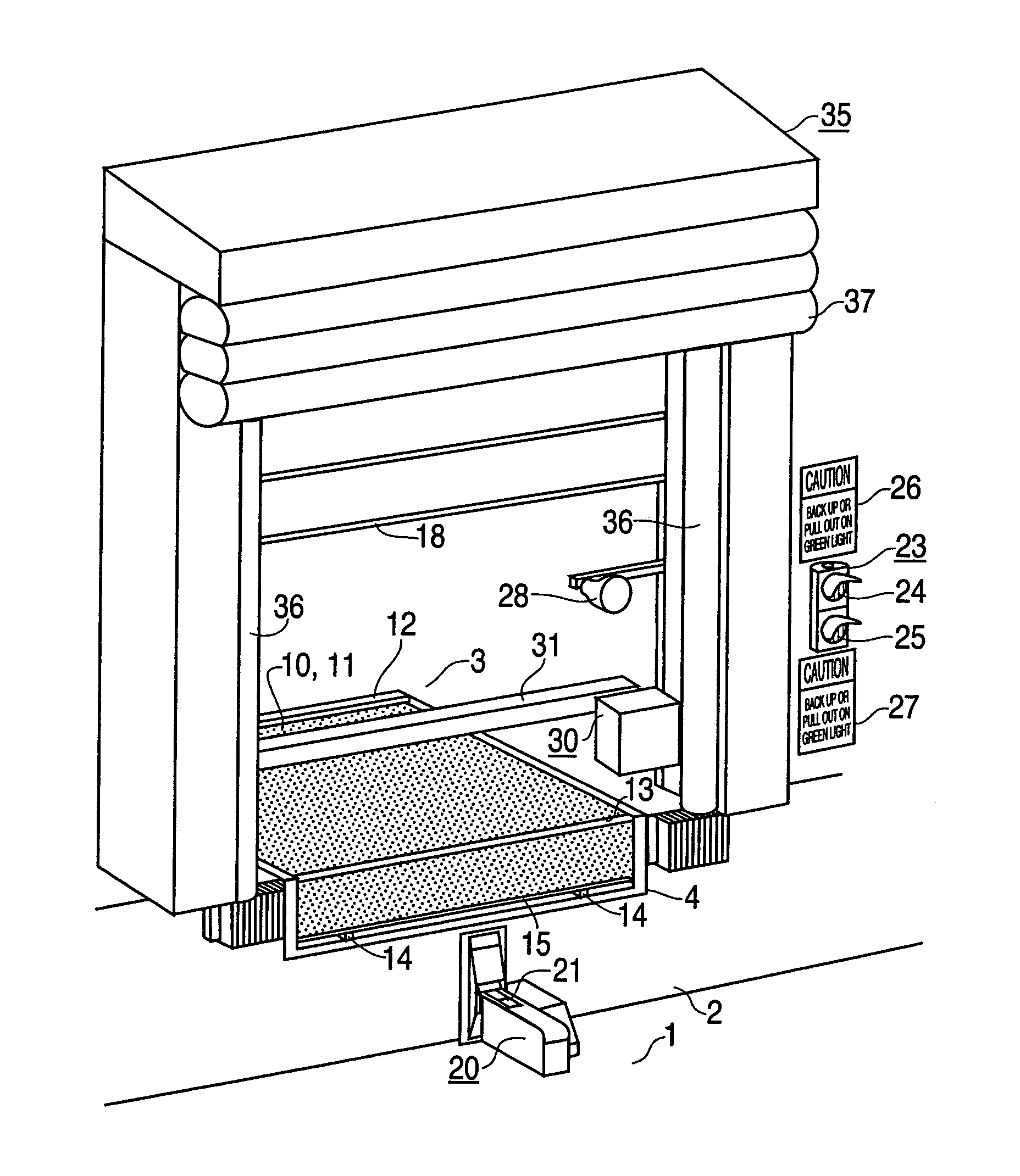
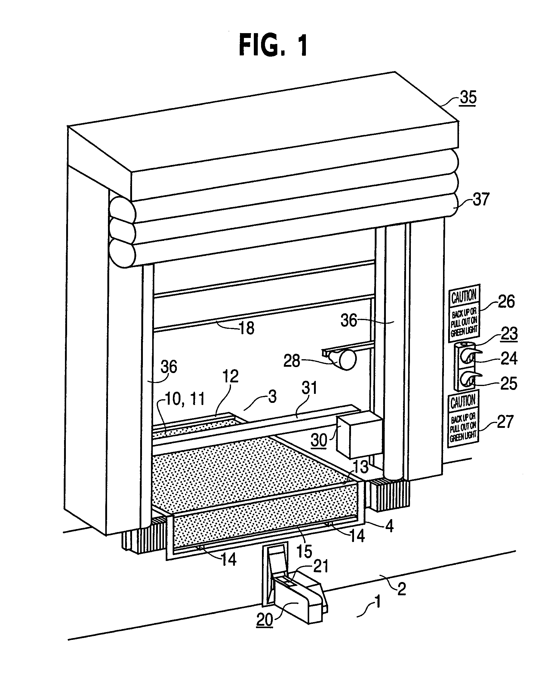
[0054]In accordance with a first optional embodiment of the invention, FIG. 4 shows a control panel 70a which operates a hydraulic dock leveler 10, FIG. 1, vehicle restraint 20 and power operated door 18. The panel has a selector switch 71 with three positions, Restraint, Door, Dock Leveler, push buttons 72, 73 and 74, (which may be referred to as operation controls, in other embodiments the operation controls may include other types of operation controls than push buttons such as levers, switches, turn key operators or other common input devices) and three indicator lights 75, 76, 77. An array of 6 operating symbols 81 through 86 indicate the operational functions of each button. Three lights 65, 66 and 67 (which may be referred to as operator signal lights) which are red, amber and green respectively, indicate to the dock operator the status of the vehicle restraint. A selector switch 78 provides an bypass for the vehicle restraint 20 similar to the Lights Only position of the sel...


PUM


Abstract

A loading dock apparatus remote control is provided. Some embodiments of the invention include a zone specific remote control for loading dock apparatus. Some optional embodiments include a selector switch to select which apparatus the single set of controls will control. Other optional embodiments automatically select the apparatus to be controlled by the single set of controls. A method of operating loading dock apparatus using a remote control is also provided.

Description

CROSS-REFERENCE TO RELATED APPLICATIONS[0001]This application claims priority to and is a continuation-in-part of two U.S. patent applications both entitled Master Control Panel for Loading Dock Equipment, both filed Apr. 18, 2002, having Ser. Nos. 10 / 124,594 (now U.S. Pat. No. 6,781,516) and Ser. No. 10 / 124,593 (now U.S. Pat. No. 6,975,226), the disclosures of which are hereby incorporated by reference in their entirety.FIELD OF THE INVENTION[0002]The present invention relates generally to control panels for loading dock equipment. More particularly, the present invention relates to a zone specific remotely operated control panel for operating loading dock equipment.BACKGROUND OF THE INVENTION[0003]Some embodiments of the invention are directed to a master control panel which simplifies the operation of loading dock equipment. In addition to having a dock leveler and overhead door, a loading dock may also have a vehicle restraint, loading light, barrier gate and inflatable shelter....

Claims


Application Information

Patent Timeline
Patent Type & Authority Patents(United States)
IPC IPC(8): G08B3/00B65G69/00B65G69/28
CPCB65G69/001B65G69/003B65G69/006B65G69/008B65G69/2876
Inventor DUVERNELL, KIMREYNARD, TERENCEALEXANDER, JAMES C.
Owner 4FRONT ENGINEERED SOLUTIONS
Learn More