Rotary-releasing device for power supply

a technology of releasing device and power supply, which is applied in the direction of coupling device connection, electrical apparatus casing/cabinet/drawer details, casing/cabinet/drawer details, etc., can solve the problems of easy damage of screws, inability to use whole electronic products, and relatively troublesome installation of such power supply, so as to facilitate access and minimize the force required for installation/detachment

Inactive Publication Date: 2007-08-21
INVENTEC CORP
View PDF10 Cites 0 Cited by
  • Summary
  • Abstract
  • Description
  • Claims
  • Application Information

AI Technical Summary

Benefits of technology

[0005]It is therefore a primary object of the present invention to provide a rotary-releasing device for power supply, which is capable of facilitating the access convenience and minimizing the force required for installing / detaching the power supply by rotating and pulling a handle of the rotary-release device.
[0006]The secondary object of the present invention is to provide a strength-saving device for installing / detaching a power supply, which a prestress is provided to the handle of the device for achieving the effects of keeping the handle still or resuming the handle to its initial position.
[0014]To make it easier for our examiner to understand the objective of the invention, its structure, innovative features, and performance, we use a preferred embodiment together with the attached drawings for the detailed description of the invention.

Problems solved by technology

The installation of such power supply is relatively troublesome because it needs a tool such as a screwdriver to install or remove the power supply.
The screws may be damaged easily after in use for a period of time that the power supply will be stuck in the housing while the power supply is damaged or busted and is required to be removed from the housing.
Under the circumstance, the whole electronic product is useless and will need to be replaced by a new one, and thus causes unnecessary waste and loss.
However, the housing 7 and the power supply body 11 sometimes cannot cannot align with each other precisely owing to the mismatch between the two that the connector 14 and the connecting member 72 can not joint properly and are damaged due to the collision.
Since the aforementioned power supply 1 needs screws for securing the same onto the housing, such arrangement not only time consuming (since it can not be detached directly) and troublesome (since it is not easy to orient the power supply into the intended position), but also fixed handle 12 takes up lots of space.
Further, it is required to apply only a parallel force to remove the detachable power supply 1, that is inconvenience and also increases the manufacturing cost.

Method used


Image

  • Rotary-releasing device for power supply
  • Rotary-releasing device for power supply
  • Rotary-releasing device for power supply

Examples


Embodiment Construction

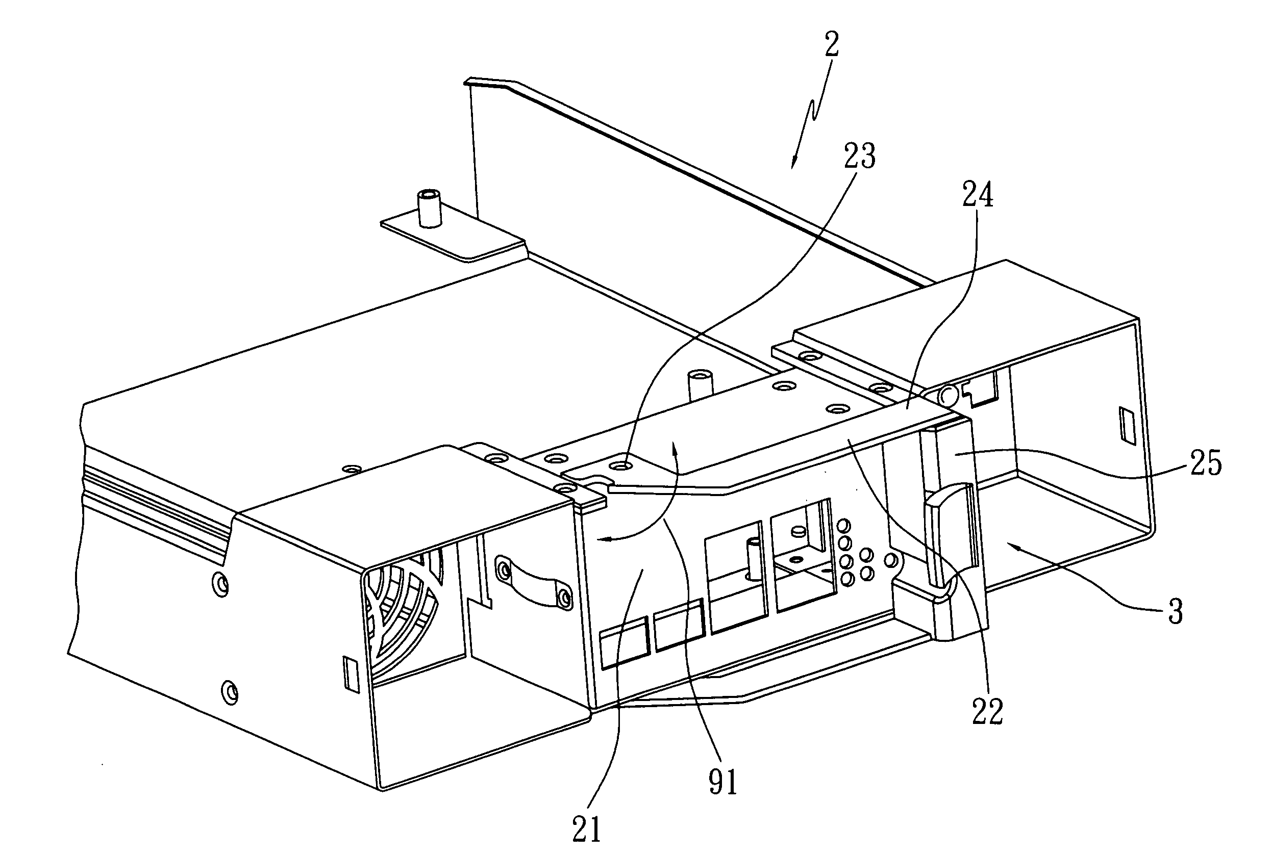
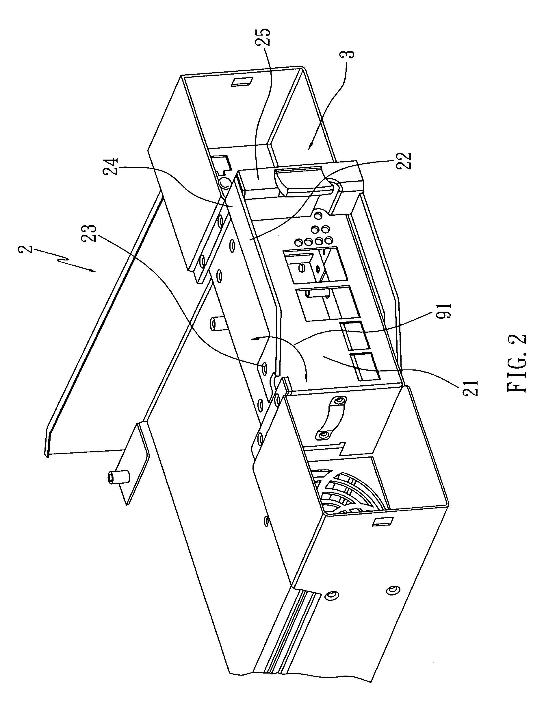
[0019]Please refer to FIG. 2, which a perspective view showing the configuring structure of a rotary-releasing device for power supply and a power supply according to the present invention. The power supply 2 is a rectangular block structure having a lateral side 21, wherein both the top and the bottom of the lateral side 21 are respectively equipped with a rotary arm 22. Each rotary arm 22 is pivotally connected to the power supply 2 by an axle end 23 to form a suspending arm structure, and the two free ends 24 of the two rotary arms 22 are connected to a handle device 25. The handle device 25 and the two rotary arms 22 can be rotated simultaneously using the axle end 23 as the axis to perform a rotating movement 91.

[0020]Please refer to FIGS. 3A and 3B for the perspective views of the rotary-releasing device for power supply according to the present invention. The rotary-releasing-device 3 for a power supply comprises a latch bracket section 31 and a handle section 32. The latch b...


PUM


Abstract

A rotary-releasing device for a power supply having two rotary arms arranged on one side thereof, and each rotary arm being coupled with the power supply by an axle end. The rotary-releasing device having: a latch bracket section, and a handle section. The latch bracket section is a suspending arm with a pressing surface, and a fixed end is coupled to a free end selected from one of the two rotary arms. The handle section has: a rotary axle body extending to a predefined height along a direction; a lifting handle extending from the rotary axle body, capable of receiving a force to enable handle section to perform a rotating movement using said direction as an axis; and a pressing arm extending from said rotary axle body to a predefined distance and connected to the lifting handle at a predefined angle.

Description

FIELD OF THE INVENTION[0001]The present invention relates to a releasing device for power supply, and more particularly, to a rotary-releasing device capable of detaching a power supply by rotating a handle.BACKGROUND OF THE INVENTION[0002]As the advance of science and technology, the electronic technology also improves accordingly such that electronic products become an essential part of our daily life. In this regard, the power supply for supplying electric power to electronic products has become extraordinarily important. The common detachable power supply sold in the market is mounted onto the housing of the electronic product by a fixing device. The installation of such power supply is relatively troublesome because it needs a tool such as a screwdriver to install or remove the power supply. The screws may be damaged easily after in use for a period of time that the power supply will be stuck in the housing while the power supply is damaged or busted and is required to be remov...

Claims


Application Information

Patent Timeline
Patent Type & Authority Patents(United States)
IPC IPC(8): A47F5/00H01R13/62H02J15/00H05K5/00H05K5/02
CPCH05K5/0086H05K5/023H05K5/0247
Inventor CHANG, LIN-WEI
Owner INVENTEC CORP
Why Eureka
Try Eureka