Injection device

a technology of injection device and syringe, which is applied in the direction of medical syringe, ampoule syringe, intravenous device, etc., can solve the problem of significant increase in the number of latching positions which has to be overcom

Active Publication Date: 2020-03-10
HASELMEIER SARL
View PDF15 Cites 0 Cited by
  • Summary
  • Abstract
  • Description
  • Claims
  • Application Information

AI Technical Summary

Benefits of technology

[0008]A simple construction results when at least one latching position is defined by at least one first latching element which is connected in a rotationally fixed manner to the housing, and at least one second latching element which is connected in a rotationally fixed manner to the setting part and which interacts with the first latching element. The latching elements here are always connected in a rotationally fixed manner to the housing or the setting part, respectively. On account of the fact that the setting part during the injection procedure is rotated back conjointly with the second latching element, it may be achieved in a simple manner that each latching position is assigned an unequivocal rotational position of the setting part in relation to the housing. Advantageously, the latching installation includes a latching part which, independently of the setting part, is axially displaceable. The latching part here is connected in a rotationally fixed manner to the housing. At least one first latching element is disposed on the latching part. In a first axial position of the latching part and of the setting part, at least one first and at least one second latching element define at least one latching position. In at least one second axial position of the latching part and of the setting part, the latching elements, independently of the rotational position of the setting part in relation to the latching part, are disengaged. The first axial position and the second axial position here are relative mutual positions of the latching part and of the setting part in the axial direction. The position of the latching part and of the setting part in relation to the housing may be variable here. On account of the latching elements being disengaged in the second axial position of the latching part and of the setting part, the setting part may be reset in relation to the latching part in the second axial position. The second axial position advantageously exists when the injection fluid is pressed out of the injection device. On account thereof, no clicks of the latching installation are audible when the injection fluid is being pressed out. The force required for pressing out the injection fluid may be minimized even in the case of latching positions which are clearly higher and perceptible when setting the amount of injection fluid to be dispensed.
[0010]Advantageously, the latching installation in each latching position permits relative rotation of the setting part in relation to the housing in the first rotation direction and blocks the relative rotation in the second rotation direction. On account thereof, reverse rotation of a dosage that has once been set is not possible. However, it may also be provided that the latching installation is conceived such that latching positions may be skipped by the operator in the second rotation direction. The injection device in particular has a spring which acts between the setting part and the housing and which biases the setting part in the second rotation direction. The spring resets the setting part to the next lesser latching position when the setting part is not located in any latching position. The spring is a torsion spring in particular. The latching installation here is advantageously conceived such that the latching installation blocks the relative rotation of the setting part in the second rotation direction at that torque that is applied by the spring. However, it may be provided that the latching installation, by applying a higher torque, may be adjusted by the operator in the second rotation direction from one latching position to the next lesser latching position. Resetting in the case of an excessive dosage that has been erroneously set may be enabled by a corresponding layout of the latching installation and of the spring. By way of the spring, it may be prevented that the setting part remains static in a position between latching positions, so that an unintended amount of injection fluid is pressed out. The injection device advantageously has a first spring which biases the latching part in the direction toward the first axial position, and a second spring which biases the setting part in the second rotation direction. However, either only the first spring or only the second spring may also be provided.
[0011]Advantageously, the injection device has a coupling which in a first position connects the setting part in a rotationally fixed manner to an operating element, and which in a second position permits relative rotation of the setting part in relation to the operating element. Advantageously, when setting an amount of injection fluid to be dispensed, the coupling is in the first position, and, when the injection fluid is being pressed out of the injection device, the coupling is in the second position. On account thereof, operation in which the operating element when setting the amount of injection fluid to be dispensed is rotated conjointly with the setting part, and in which the operating element when the amount of injection fluid to be dispensed is being pressed out is displaced in the proximal direction, is possible. On account of the setting part, which is rotated in relation to the housing when the injection fluid is being pressed out, also being able to rotate in relation to the operating element, the operating element does not have to be rotated when the amount of injection fluid to be dispensed is being pressed out. Advantageously, when the amount of injection fluid to be dispensed is being pressed out, the operating element is guided along at least part of the displacement path thereof in a rotationally fixed manner in relation to the housing.
[0012]Adjustment of the coupling from the first to the second position is advantageously performed by displacing the operating element in the proximal direction. The latching part is advantageously coupled in the axial direction to the operating element in such a manner that movement of the operating element in the proximal direction causes movement of the latching part in the proximal direction. On account thereof, it is ensured that the latching installation is not active when the coupling is located in the second position, that is, when an injection is possible. A simple construction results when the latching part and the operating element are interconnected in an axially fixed manner and so as to be rotatable in relation to one another. On account thereof, a spring which biases the latching part in the axial direction also acts on the operating element. The spring advantageously acts on the operating element in the distal direction such that the operating element when initiating an injection has to be moved in the proximal direction, counter to the force of the spring.
[0013]A simple configuration of the coupling results when the coupling has a first toothing on the setting part which interacts with a second toothing on the operating element. Since the relative position of the operating element in relation to the setting part may be modified during operation, when the operating element is rotated in relation to the housing when setting the amount of injection fluid to be dispensed, but is guided in a rotationally fixed manner in relation to the housing during the injection procedure, the coupling has to enable a rotationally fixed connection between the operating element and the setting part in all theoretically possible rotational positions of the operating element and of the setting part in relation to one another. This may be achieved in a simple manner by a toothing of correspondingly fine configuration.
[0014]Advantageously, the setting part is connected by way of a first threaded connection to the housing, and when setting an amount of injection fluid to be dispensed, additionally to rotating in the first rotation direction, moves in the distal direction, and when a set amount of injection fluid is being pressed out, additionally to rotating in the second rotation direction, moves in the proximal direction. In one preferred embodiment, the distance along which the setting part is moved in the distal direction corresponds to the distance which has to be covered by a dosing piston of the injection device in order to press out the set amount of injection fluid. This is advantageous in particular when a spring which biases the setting part in the second rotation direction acts between the setting part and the housing. The rotation of the setting part in the second rotation direction, causing the set amount of injection fluid to be dispensed, here is advantageously caused by the spring such that pressing out the set amount of injection fluid is automatically performed once the latching position has been released.

Problems solved by technology

However, this leads to a significantly increased number of latching positions which have to be overcome by the operator when setting the dosage.

Method used


Image

  • Injection device
  • Injection device
  • Injection device

Examples


Embodiment Construction

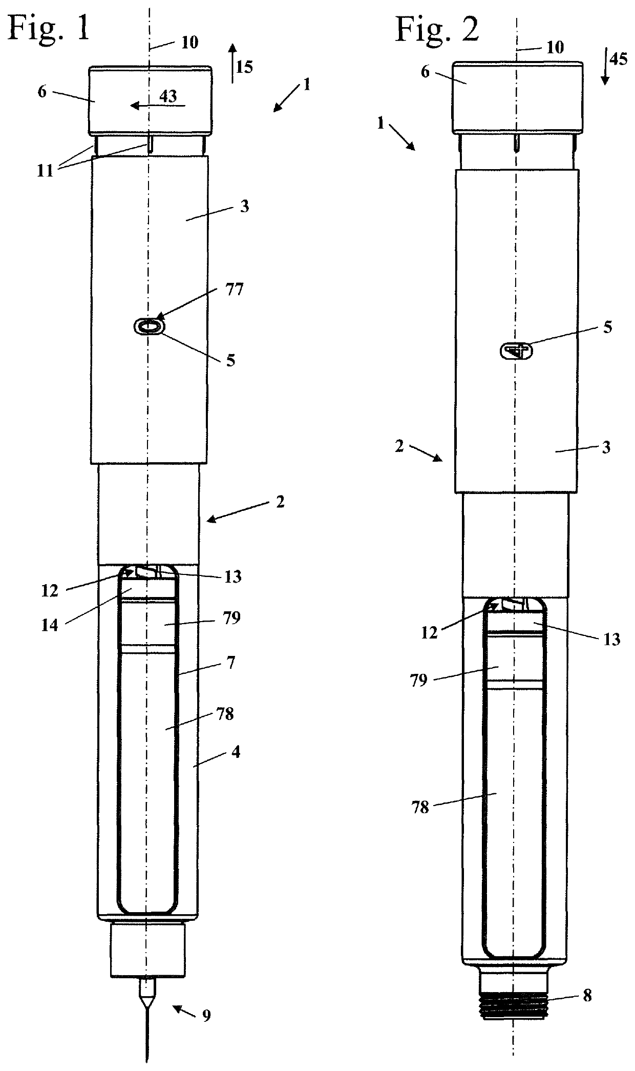
[0044]An injection device 1 which serves for setting an envisaged amount of injection fluid and for pressing the latter out of a cartridge held in the injection device 1 is shown in FIGS. 1 and 2. The injection device 1 has a housing 2 which includes an upper housing part 3 and a holder 4 which is disposed on the upper housing part 3. The cartridge, which includes an advantageously transparent container 78 having injection fluid, and a plug 79 which is disposed in the container 78 and is advantageously visible from the outside, is disposed in the holder 4. The holder 4 in the embodiment has two viewing windows 7 which are disposed so as to be mutually opposite and through which the operator sees how much injection fluid is still contained in the container 78. A dosing piston 12 of the injection device 1 bears on the plug 79. The dosing piston 12 has a piston rod 13, a piston disk 14 being held thereon. The piston disk 14 of the dosing piston 12 bears on the plug 79 of the container ...


PUM


Abstract

An injection device includes a housing and a setting part configured to, in relation to said housing, rotate in a first rotational direction when an amount of injection fluid to be dispensed is being set. The setting part rotates in a second rotational direction counter to the first rotational direction when the injection fluid is pressed out of the injection device. A latching unit defines at least one latching position of the setting part and acts between the setting part and the housing. The latching unit is active at least when the amount of injection fluid to be dispensed is set and each of the latching positions has an unequivocal rotational position of the setting part in relation to the housing assigned thereto.

Description

CROSS REFERENCE TO RELATED APPLICATIONS[0001]This application is a continuation application of international patent application PCT / EP2015 / 000206, filed Feb. 3, 2015, designating the United States and claiming priority from German application 20 2014 001 135.4, filed Feb. 5, 2014, and the entire content of both applications is incorporated herein by reference.BACKGROUND OF THE INVENTION[0002]An injection device which as a setting part has a graduated tube is known from U.S. Pat. No. 8,747,367. When setting an amount of injection fluid to be pressed or squeezed out, the graduated tube is moved in the distal direction. The graduated tube is moved in the opposite direction when the amount of injection fluid to be squeezed out or dispensed is being pressed out. The graduated tube is connected to the housing by way of a threaded connection such that the graduated tube, in addition to the movement in the distal or proximal direction, is also rotated in relation to the housing. Moreover, t...

Claims


Application Information

Patent Timeline
Patent Type & Authority Patents(United States)
IPC IPC(8): A61M5/315A61M5/24
CPCA61M5/24A61M5/31593A61M5/3155A61M5/31585A61M5/31551A61M5/3156
Inventor KEITEL, JOACHIM
Owner HASELMEIER SARL
Why Eureka
Try Eureka