Laminated-type multi-joint portion drive mechanism and manufacturing method therefor, grasping hand and robot arm provided with the same
a technology of multi-joint parts and drive mechanisms, which is applied in the direction of program-controlled manipulators, load-engaging elements, gripping heads, etc., can solve the problems of robot hands, large number of component parts, and high assembly costs, and achieves limited research use, the possibility that the actuators might no longer sufficiently flex, and the effect of increasing the number of parts
- Summary
- Abstract
- Description
- Claims
- Application Information
AI Technical Summary
Benefits of technology
Problems solved by technology
Method used
Image
Examples
first embodiment
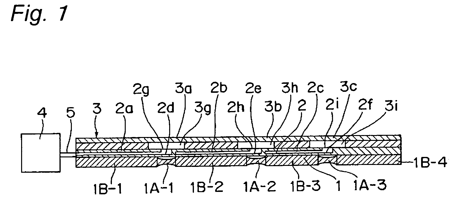
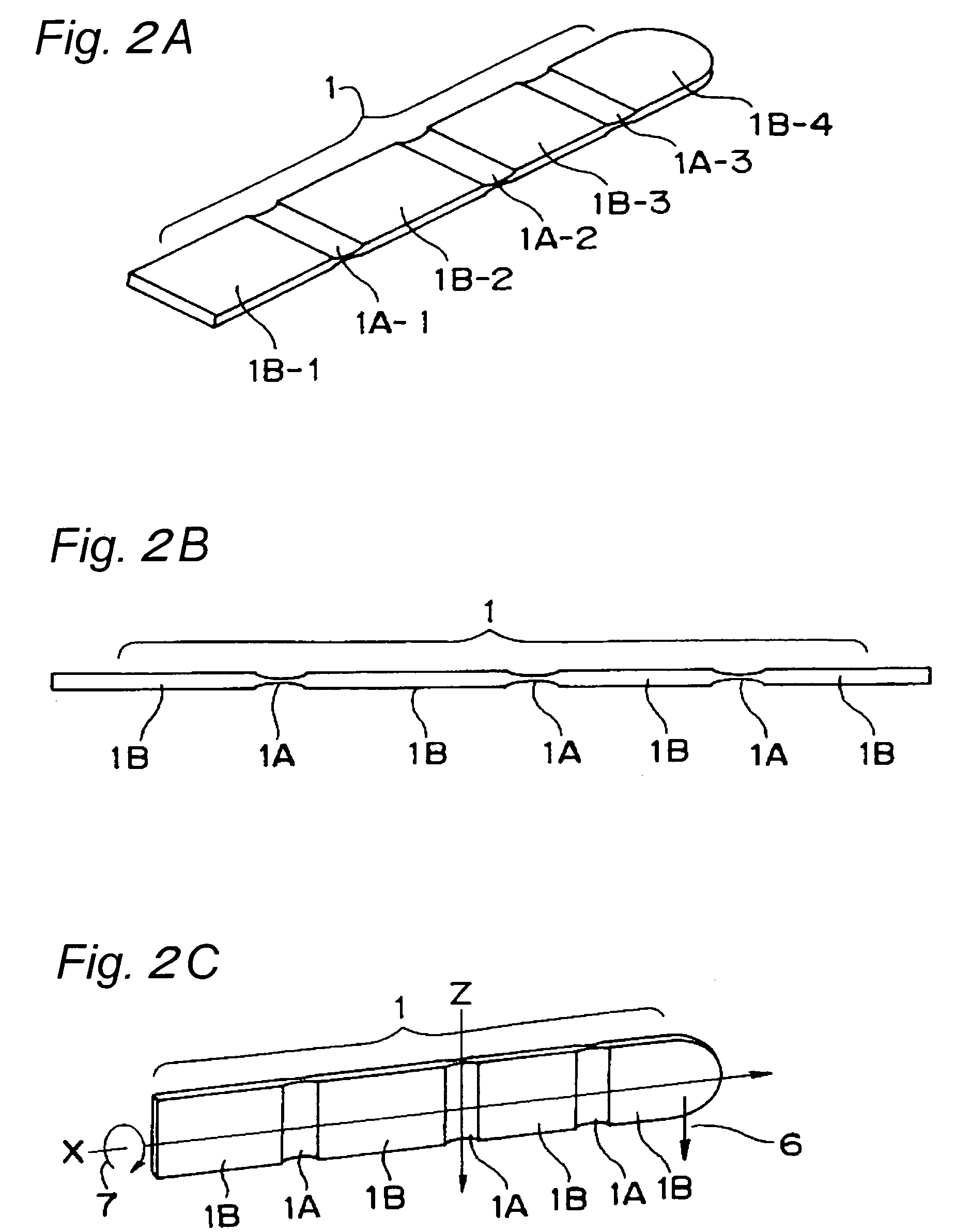
[0086]FIG. 1 is a sectional view of a laminated-type multi-joint portion drive mechanism according to a first embodiment of the present invention. The laminated-type multi-joint portion drive mechanism shown in FIG. 1 is formed through steps of stacking a plate-shaped laminated-type pneumatic tube formation member 2 and a planar-type joint-portion flexural deformation member 3 on a bone member 1 having elastic hinge portions 1A provided at a plurality of joint portions, respectively, and then tightly joining these members by adhesively bonding them together with an adhesive such as polyimide-based adhesive. This multi-joint portion drive mechanism includes a pneumatic drive source 4 such as an air cylinder for feeding compressed air or the like, a pneumatic pressure introduction tube 5 for implementing a pneumatic introductory tube connected to the pneumatic drive source 4, the laminated-type pneumatic tube formation member 2 having gas passage through holes 2g, 2h, 2i connected to ...
second embodiment
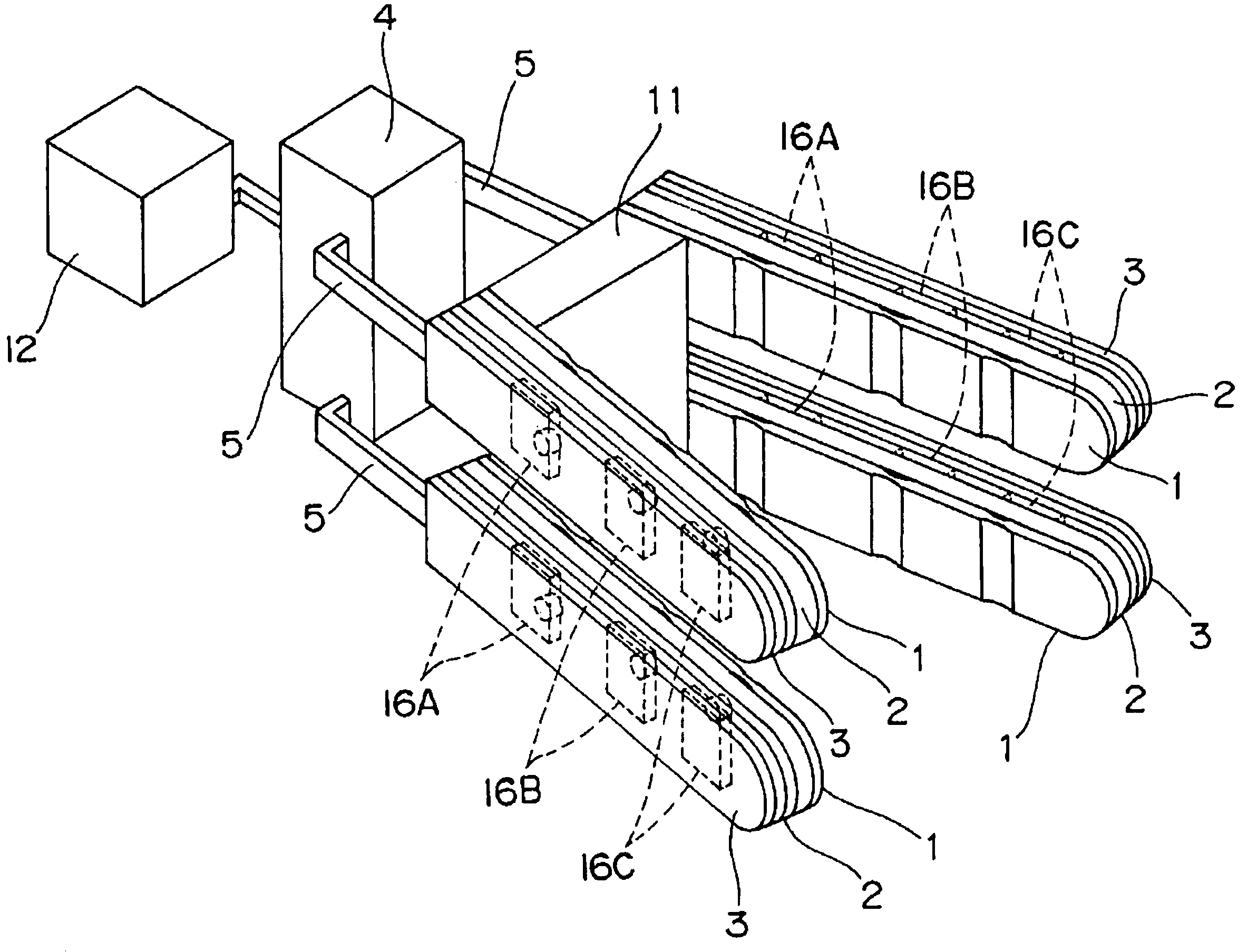
[0109]FIGS. 10 and 11 are a perspective view and a block diagram, respectively, of a grasping hand provided with the laminated-type multi-joint portion drive mechanism of the first embodiment, where a grasping function is given by providing a plurality, e.g., one pair of laminated-type multi-joint portion drive mechanisms face to face and left-and-right symmetrical. With a root of each bone member 1 serving as a junction portion, the laminated-type multi-joint portion drive mechanisms are placed and fixed at a fixing portion 11 so as to confront each other.
[0110]The control section 12 controls drive of the pneumatic drive source 4, and also controls opening and closing of first solenoid valves 17a, 17a interposed on left-and-right first laminated-type pneumatic tubes 2a, 2a, opening and closing of second solenoid valves 17b, 17b interposed on left-and-right second laminated-type pneumatic tubes 2b, 2b, and opening and closing of third solenoid valves 17c, 17c interposed on left-and-...
third embodiment
[0126]FIG. 22 is a perspective view of a robot which uses a laminated-type multi-joint portion drive mechanism according to a third embodiment of the present invention and in which the grasping hand of FIG. 12 according to the second embodiment is provided at an end of the robot arm of the laminated-type multi-joint portion drive mechanism of FIG. 1.
[0127]Robot arm 21 of FIG. 22 is constructed by using the laminated-type multi-joint portion drive mechanism shown in FIG. 1 according to the first embodiment, with its drive principle being as described in the first embodiment. The robot arm 21 is connected to a robot arm prop 22 having a pneumatic drive source via a rolling mechanism 23, and further a grasping hand 24 shown in FIG. 12 according to the second embodiment is connected to an end portion of the robot arm 21. By drive of the robot arm 21, the grasping hand 24 is positioned to an arbitrary position within a movable range to grasp an object. This robot arm 21, which uses the l...
PUM
 Abstract
Description
Claims
Application Information
 - R&D
- Intellectual Property
- Life Sciences
- Materials
- Tech Scout
- Unparalleled Data Quality
- Higher Quality Content
- 60% Fewer Hallucinations
Browse by: Latest US Patents, China's latest patents, Technical Efficacy Thesaurus, Application Domain, Technology Topic, Popular Technical Reports.
© 2025 PatSnap. All rights reserved.Legal|Privacy policy|Modern Slavery Act Transparency Statement|Sitemap|About US| Contact US: help@patsnap.com


