Golf club and method for manufacturing the same

a golf club and manufacturing method technology, applied in the field of golf clubs, can solve the problems of insufficient joining strength and inability to obtain great adhesion, and achieve the effect of enhancing the adhesion of the edge frame and the shell body, and enhancing the strength of the golf club

Inactive Publication Date: 2007-08-21
ENDO MFG COMPANY
View PDF17 Cites 126 Cited by
  • Summary
  • Abstract
  • Description
  • Claims
  • Application Information

AI Technical Summary

Benefits of technology

[0006]The present invention has been made to solve the above problems. It is, accordingly, an object of the present invention to enhance the coherence of metal and resin so as to sufficiently enlarge joining strength thereof in a golf club in which a shaft is connected to a golf club head employing a hollow structure such that the resin is embedded in the metal of an outer shell.
[0008]By employing this structure, the shell body made from resin envelops the edge frame made from metal. Accordingly, joining thereof can be enhanced, and thus strength of the golf club head can be enhanced.
[0012]According to the above-explained method, the molten resin of the shell body envelops the inner edge of the edge frame made by casting manner so that the shell body and the edge frame are integrated with each other. Therefore, adhesiveness of the edge frame and the shell body can be enhanced, and thus strength of the golf club can be enhanced.

Problems solved by technology

In those techniques, however, there is a problem that great adhesion can not be obtained when bonding them, and thus sufficient joining strength can not be obtained.

Method used


Image

  • Golf club and method for manufacturing the same
  • Golf club and method for manufacturing the same
  • Golf club and method for manufacturing the same

Examples


first embodiment

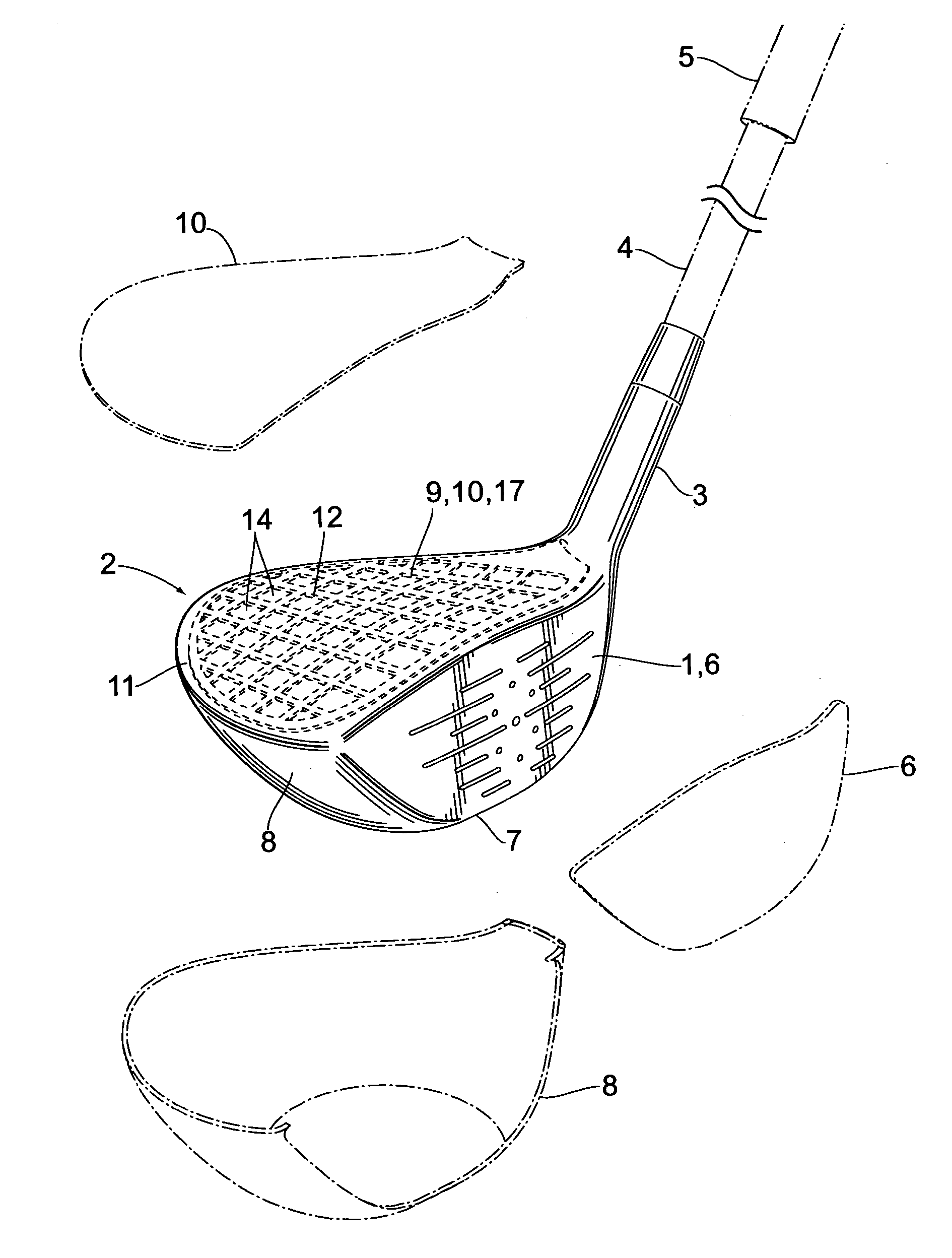
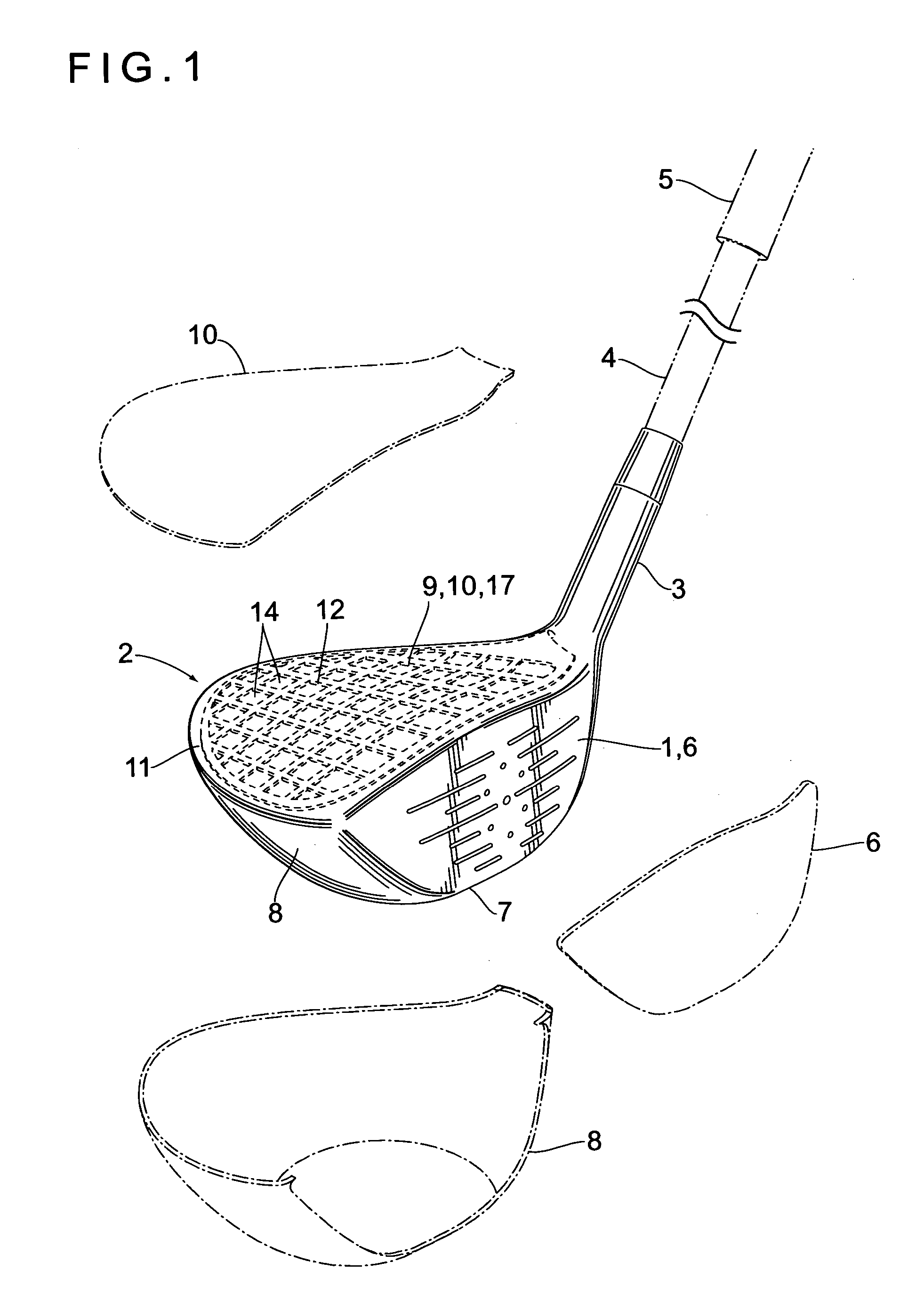
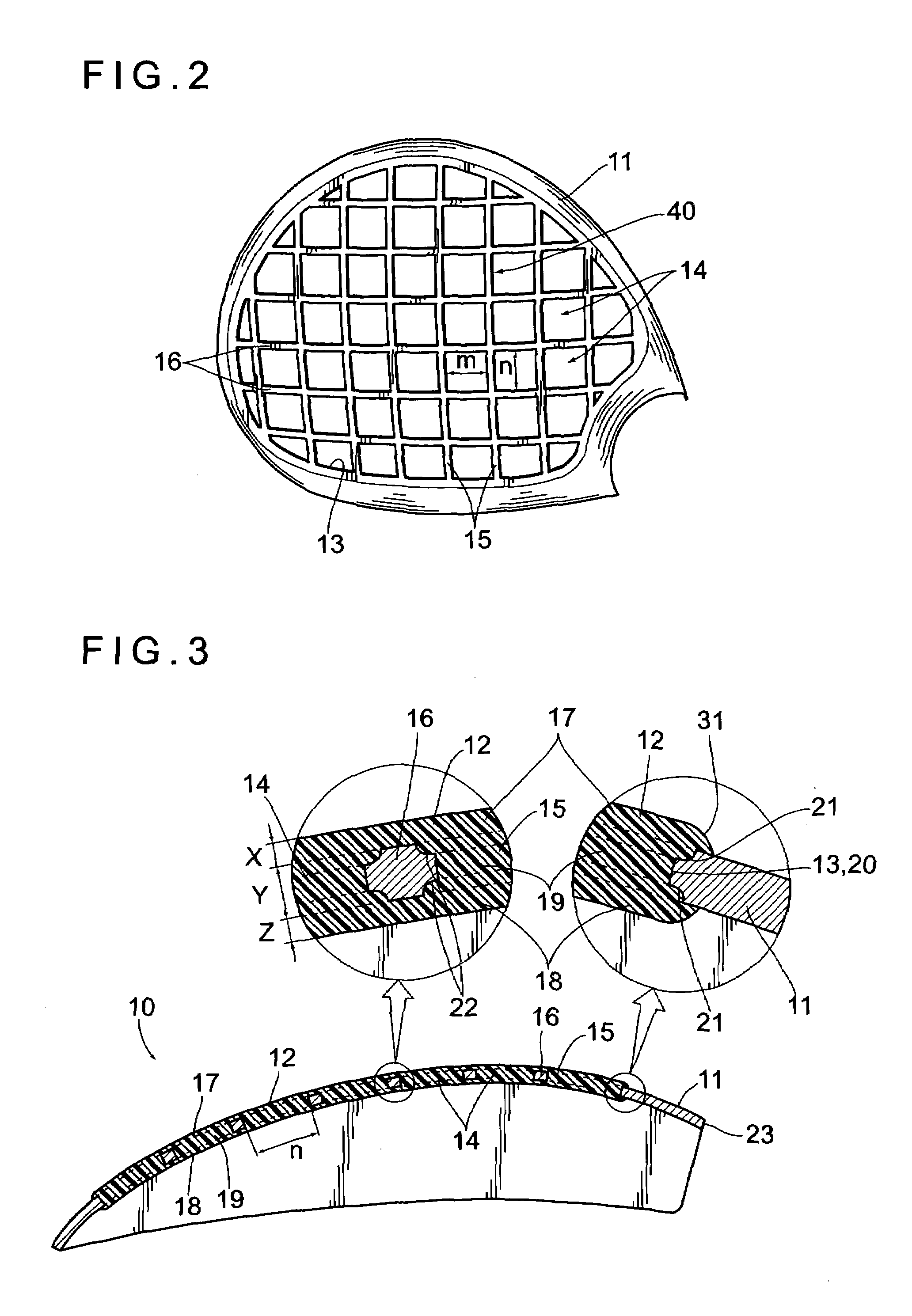
[0026]FIGS. 1 to 4 show a wood type golf club head according to a first embodiment of the present invention. This wood type golf club comprises: a golf club head 2 (hereinafter, head 2) having a face 1 on its front; a shaft 4 (shown by chain double dashed lines) having a bottom end connected to a neck 3 formed on one side of the head 2; and a grip 5 provided on the upper portion of the shaft 4. As shown by chain lines, the head 2 employs a hollow structure formed by joining a plurality of partial outer members so as to include: a partial face portion member 6 forming the face 1; a partial sole-peripheral side surface portion member 8 forming a sole 7, right, left and rear portions of the head 2; a partial crown portion member 10 forming a crown 9; and a neck member (not shown) formed in a cylindrical shape protruding from the one side of the head 2 so as to form the neck 3. Each edge, etc. of the partial shell members are joined by welding such as laser welding so as to be integrate...

second embodiment

[0036]FIG. 5 shows a partial crown portion member 10 of a golf club according to a second embodiment of the present invention. The same reference numbers will denote the same structure portions as those of the golf club according to the first embodiment, while detailed explanations thereof will be omitted. In the second embodiment, the plurality of first reinforced ribs 15 are provided, in parallel to the front-rear direction, on the window opening 13 which is inwardly provided relative to the edge frame 11. By these first reinforced ribs 15, durability of the edge frame 11 along the front-rear direction can be enhanced.

third embodiment

[0037]FIG. 6 shows a partial crown portion member 10 of a golf club according to a third embodiment. The same reference numbers will denote the same structure portions as those of the golf club according to the first embodiment, while detailed explanations thereof will be omitted. In the third embodiment, the plurality of second reinforced ribs 16 are provided in parallel to the right-left direction, on the window opening 13 which is provided inwardly relative to the edge frame 11. By these second reinforced ribs 16, durability of the edge frame 11 along the right-left direction can be enhanced.

[0038]Various embodiments and changes may be made thereonto without departing from the broad spirit and scope of the invention. The above-described embodiments are intended to illustrate the present invention, not to limit the scope of the present invention. The scope of the present invention is shown by the attached claims rather than the embodiments. Various modifications made within the me...


PUM


Abstract

The partial crown portion member comprises: the edge frame made from metal; and the shell body provided inside the edge frame and made from resin enveloping the inner edge of the edge frame. Inside the edge frame, the plural through-holes penetrating the front surface of the edge frame to the rear surface thereof are provided, while the shell body is inserted in the through-holes by casting manner. Since the front and rear surfaces of the inner edge of the edge frame, the through-holes are enveloped by casting manner, the adhesiveness thereof can be enhanced.

Description

BACKGROUND OF THE INVENTION[0001]1. Field of the Invention[0002]The present invention relates to a golf club and a method for manufacturing the same.[0003]2. Description of the Related Art[0004]As conventional known techniques of joining a metallic outer shell and a fiber-reinforced-plastic-made outer shell in order to configure a head body employing a hollow structure, Japanese Unexamined Patent Publication No. 2003-205055 discloses ones such that: bonding a joining portion of the fiber-reinforced-plastic-made outer shell to both surfaces of a joining portion of the metallic outer shell; or forming a through-hole on the joining portion of the metallic outer shell so as to obtain joining strength of the metallic outer shell relative to the fiber-reinforced-plastic-made outer shell.[0005]In those techniques, however, there is a problem that great adhesion can not be obtained when bonding them, and thus sufficient joining strength can not be obtained.SUMMARY OF THE INVENTION[0006]The ...

Claims


Application Information

Patent Timeline
Patent Type & Authority Patents(United States)
IPC IPC(8): A63B53/04A63B102/32
CPCA63B53/04A63B53/0466A63B2053/0416A63B2053/045A63B53/047A63B2209/02A63B53/0416A63B53/045A63B60/006A63B60/00
Inventor KOBAYASHI, KENJI
Owner ENDO MFG COMPANY
Why Eureka
Try Eureka