Tie plate
a tie plate and tie plate technology, applied in the field of insulated tie plates, can solve the problems of not being able to take the high-rail traffic, fail prematurely, and high cost of non-metallic insulating tie plates, and achieve the effect of expanding the width of the base pla
- Summary
- Abstract
- Description
- Claims
- Application Information
AI Technical Summary
Benefits of technology
Problems solved by technology
Method used
Image
Examples
second embodiment
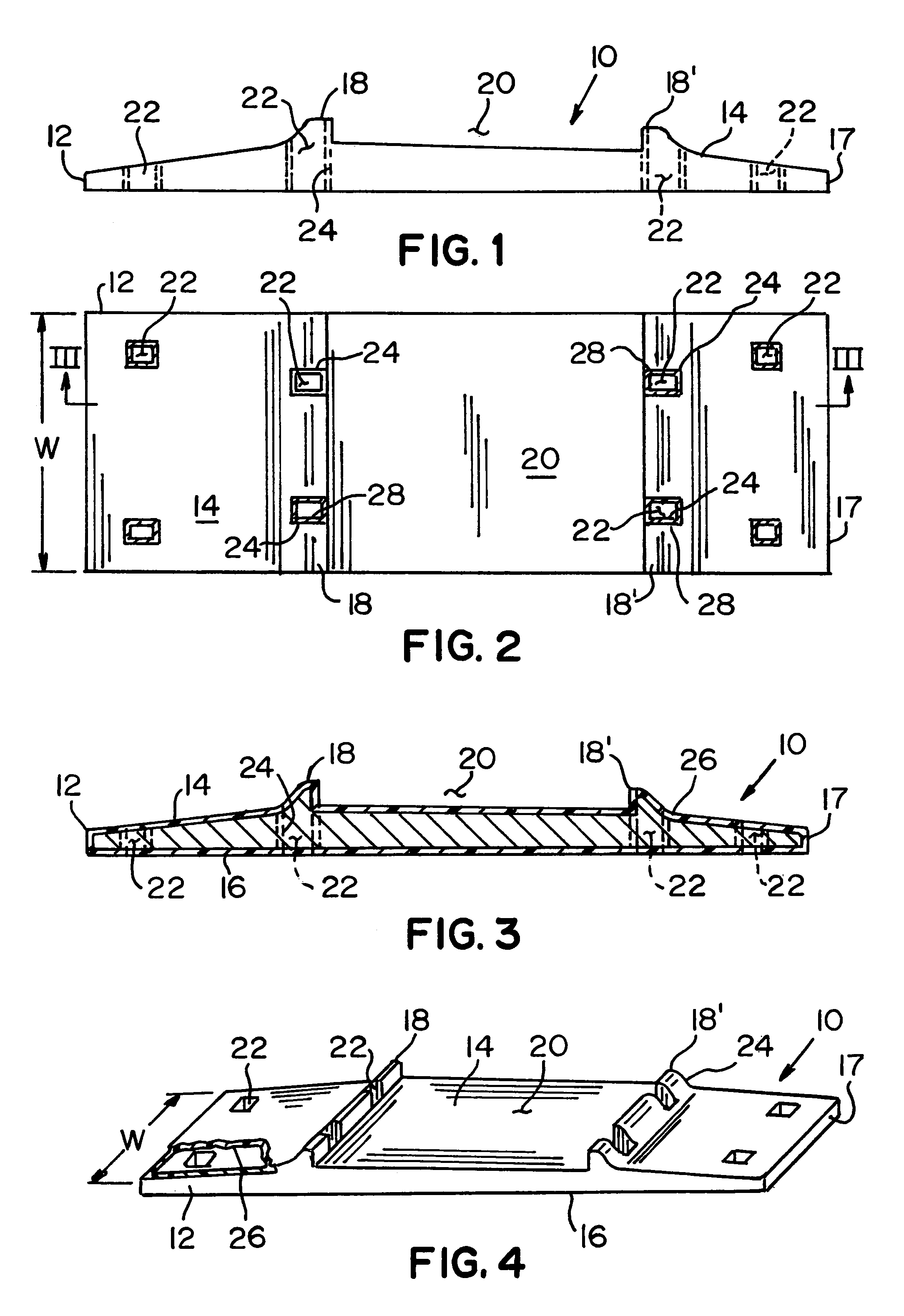
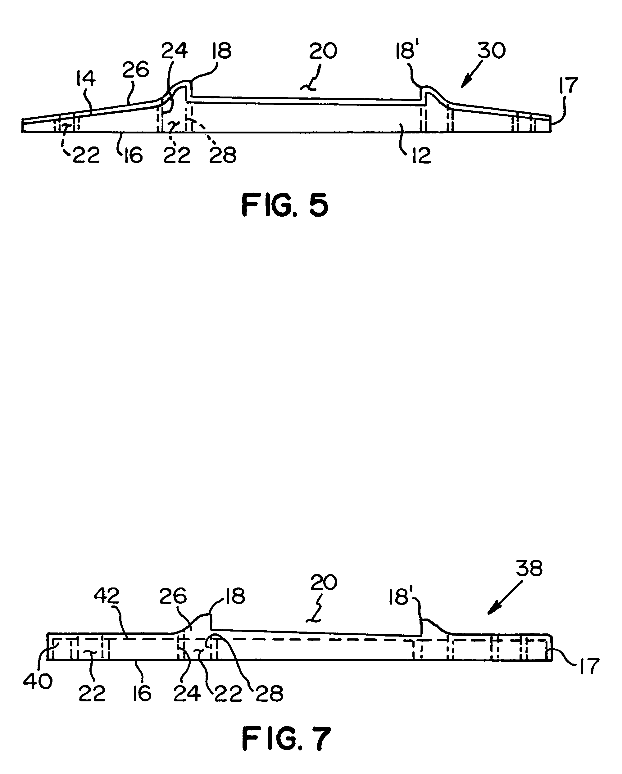
[0025]FIG. 5 shows a tie plate 30, which is similar to a tie plate 10 except for the below noted difference. Like reference numerals are used for like elements. In tie plate 30, only the first surface 14 of the base plate 12 is covered by a layer. 26 of electrically-insulating material instead of the entire base plate 12 as in tie plate 10.
third embodiment
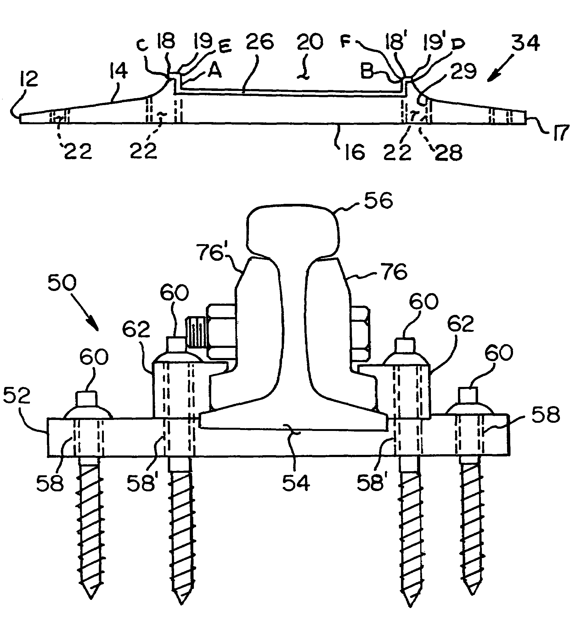
[0026]FIG. 6 shows a tie plate 34, which is similar to a tie plate 30 except for the below noted difference. Like reference numerals are used for like elements. In tie plate 34, only the recessed area 20 and inner surface of the shoulder members 18, 18′ on the first surface 14 of the base plate 12 are covered by a layer 26 of electrically-insulating material instead of the entire first surface 14 as in tie plate 30. The layer 26 includes legs A and B connected by a base thereby defining a U-shaped cross section. Optionally, the layer 26 may include lips 19 and 19′ depending from legs A and B of the layer 26, wherein the lips 19, 19′ cover a shoulder member upper surface C and D of the shoulder members 18, 18′, respectively. The layer 26 includes leg upper surfaces E and F positioned above the shoulder member upper surfaces C and D. Preferably, the layer 26 is made of UHMWPE or laminated fiber glass, but other insulating materials may be used.
fourth embodiment
[0027]FIG. 7 shows a tie plate 38, which is similar to a tie plate 30 except for the below noted difference. Like reference numerals are used for like elements. Tie plate 38 includes a rectangular-shaped base plate 40 having a planar first surface 42. The layer 26 of electrically-insulating material also covers the first surface 42 and the peripheral edges 17 of the base plate 40. The overall shape of the tie plate 38 is similar to tie plates 10, 30, and 34 except that the pair of longitudinal-extending shoulder members 18, 18′ are made of an electrically-insulating material.
[0028]FIG. 8 shows a tie plate assembly 50 for a railroad rail 56 made in accordance with the present invention, wherein like reference numerals are used for like elements. The tie plate assembly 50 includes an electrically-insulated tie plate 52 having a recessed area 54 adapted to receive the railroad rail 56, a plurality of slots 58, 58′ defined on the tie plate 52, and at least one fastener 60 passing throug...
PUM
 Abstract
Description
Claims
Application Information
 - R&D
- Intellectual Property
- Life Sciences
- Materials
- Tech Scout
- Unparalleled Data Quality
- Higher Quality Content
- 60% Fewer Hallucinations
Browse by: Latest US Patents, China's latest patents, Technical Efficacy Thesaurus, Application Domain, Technology Topic, Popular Technical Reports.
© 2025 PatSnap. All rights reserved.Legal|Privacy policy|Modern Slavery Act Transparency Statement|Sitemap|About US| Contact US: help@patsnap.com


