Push button latch release assembly

a technology of latch release and push button, which is applied in the direction of carpet fasteners, keyhole guards, roofs, etc., can solve the problems of complex construction of known mechanisms and too large dimensions, and achieve the effect of easy identification and us

Inactive Publication Date: 2007-08-28
WESCO DISTRIBUTION
View PDF9 Cites 43 Cited by
  • Summary
  • Abstract
  • Description
  • Claims
  • Application Information

AI Technical Summary

Benefits of technology

[0009]In a preferred embodiment the passageway in the shaft can be the form of an axial slot and an emergency actuator mechanism can be employed to release the spring latches even if the button cylinder is locked. The emergency actuator mechanism can include a sleeve which is axially positioned around the shaft, the sleeve including opposed holes through which the latch cord extends. Moving the sleeve away from the base of the push button actuator housing by use of a pull cord will cause the sleeve to move the latch cord along the axial slot in the (stationary) shaft and to become extended (lengthened) between the posts, thus releasing the spring latches to which the latch cord is connected. This embodiment is useful, for example, when employed on a tonneau cover where the push button actuator, spring latches and latch cord are not accessible to someone who could become trapped under the cover. A handle attached to the pull cord can be adored with fluorescent paint or fluorescent patches, and it can be removably attached, e.g., by hook and loop fastening means, to the underside of the top of the tonneau cover for easy identification and use.

Problems solved by technology

However, the known mechanisms are in many cases complicated in construction, requiring many parts, or are too large in dimensions for many installation situations.

Method used


Image

  • Push button latch release assembly
  • Push button latch release assembly
  • Push button latch release assembly

Examples


Embodiment Construction

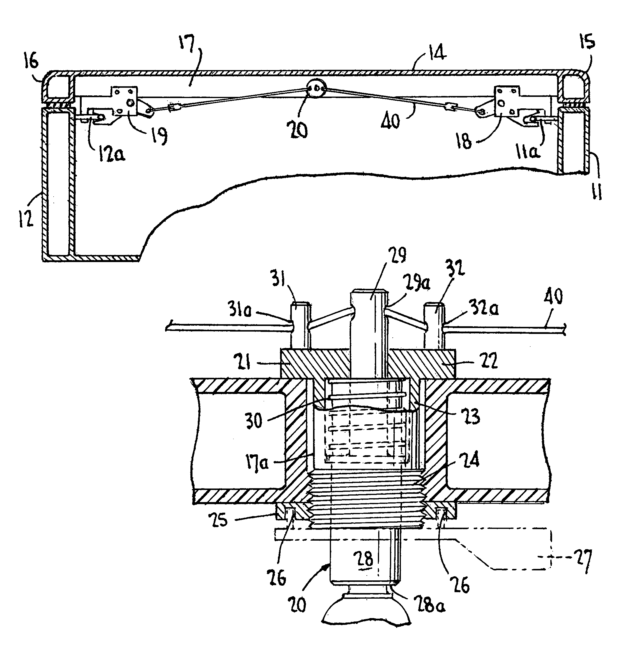
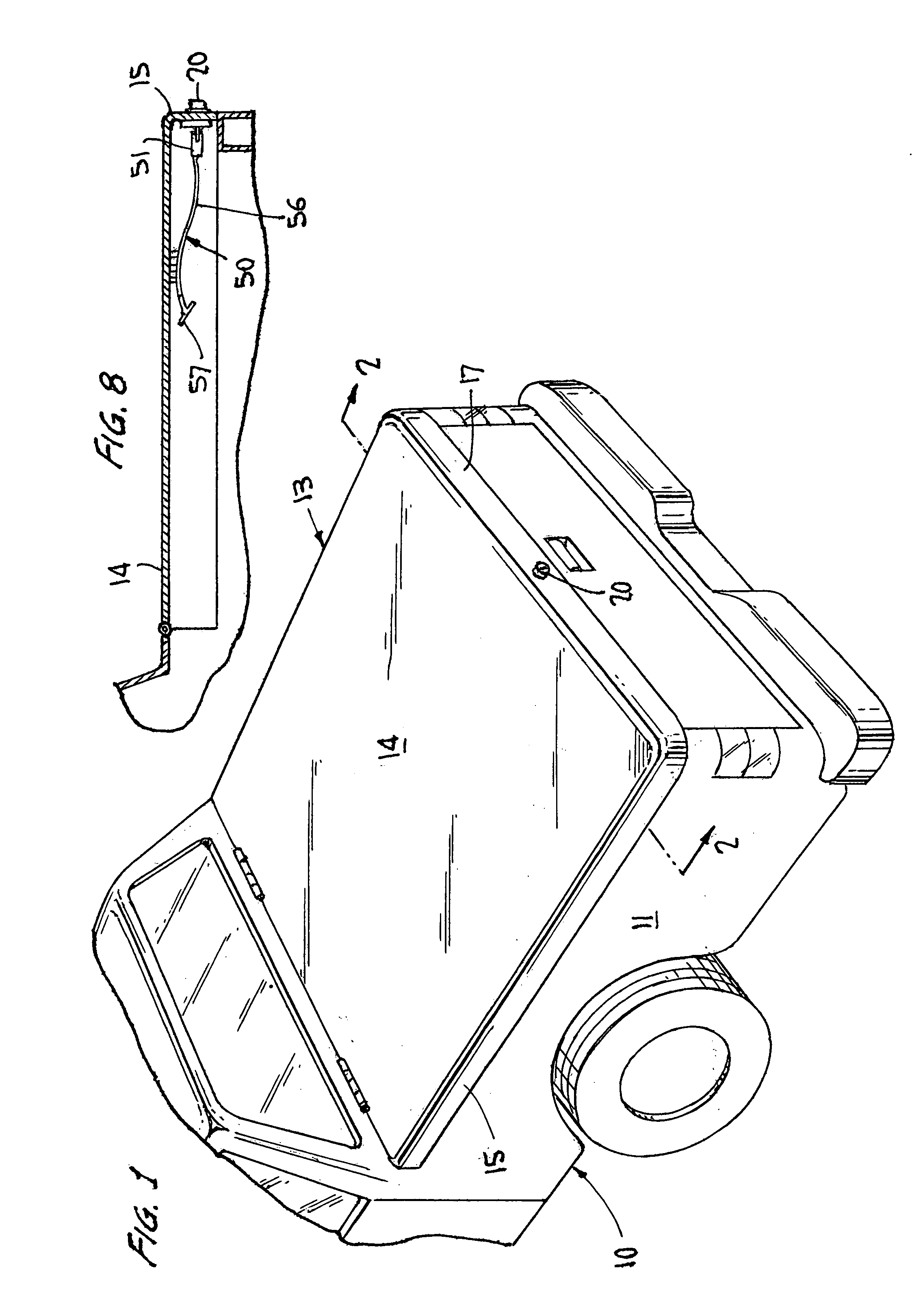
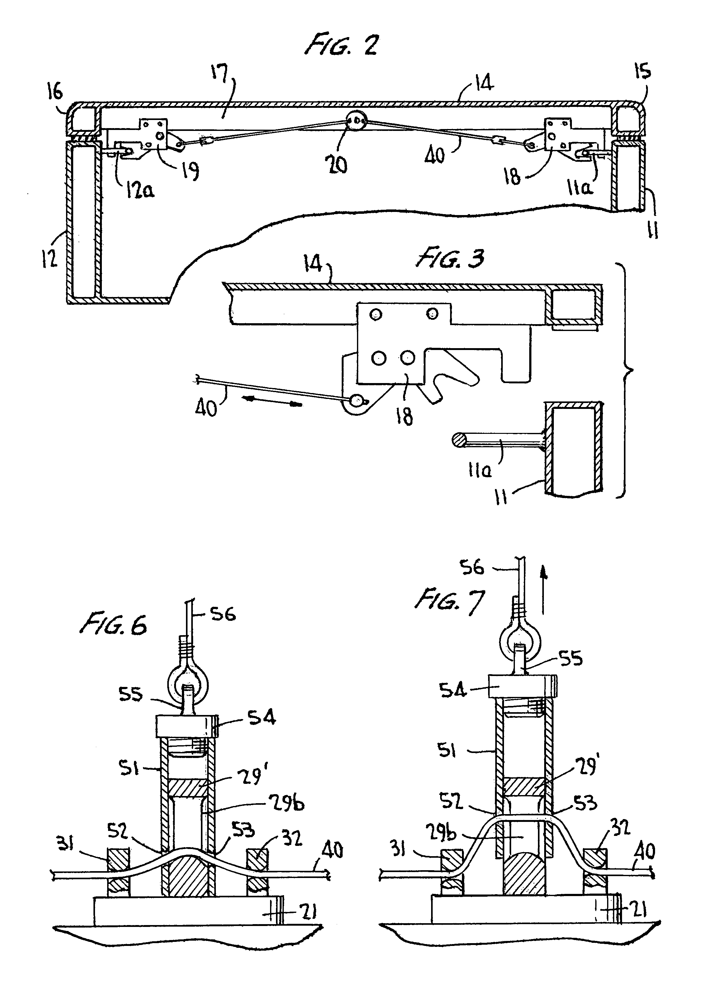
[0017]A first preferred embodiment of push button latch release assembly according to the present invention is seen in FIGS. 1, 4 and 5. It includes a push button actuator 20 and a latch cord 40 which is threaded through the push button actuator and connected to two spring latches located on opposite sides of the push button actuator. As shown in FIGS. 1-3, in a preferred application of the push button latch release assembly the push button actuator 20 is located in an opening 17a in the rear side 17 of a tonneau cover 13, which is mounted over the bed of a flatbed truck 10. The tonneau cover 13 includes a top 14 and opposite left and right sides 15 and 16. The latch cord 40 connects at its opposite ends to release levers of conventional rotary spring latches 18 and 19 mounted at opposite sides of the tonneau cover and which can respectively lock on brackets 11a and 12a extending inwardly from the sides 11 and 12 of the truck.

[0018]The push button actuator 20 includes a housing 21 h...


PUM


Abstract

A push button latch release assembly includes a push button actuator and a latch cord which extends through the push button actuator and connects at its opposite ends to release arms of respective rotary spring latches. The push button actuator includes a housing having a base and a tubular barrel, and a button cylinder which is axially movable in the barrel. The button cylinder includes a shaft which extends through a hole in the base of the housing and the base mounts two posts which are located on opposite sides of the shaft. The latch cord extends through respective guide channels in the posts and a passageway through the shaft. Pressing the button cylinder moves the shaft so that the latch cord is extended between the posts and the ends of the latch cord are drawn in, releasing the release arms.

Description

CROSS-REFERENCE TO RELATED APPLICATION[0001]This application claims the benefit of U.S. Provisional Application No. 60 / 619,029, filed Oct. 18, 2004.BACKGROUND OF THE INVENTION[0002]1. Field of the Invention[0003]The present invention relates to latch release mechanisms, and more particularly to latch release mechanisms that can simultaneously release two separated latches.[0004]2. The Prior Art[0005]Latch release mechanisms capable of releasing two separated latches that connect two members together are well known. A mechanism of this type for barn releasing latches connecting a barn door to a barn was patented in 1877 (see U.S. Pat. No. 1,971,15). Latch release mechanisms of this type find modern use in unlatching doors of vehicles and industrial cabinets. See, for example, U.S. Pat. Nos. 2,839,912, 3,027,188, 4,892,338 and 6,685,240. Such mechanisms can be used in releasing the latches that are used to lock a tonneau cover in position over the bed of a truck. See, for example, U.S...

Claims


Application Information

Patent Timeline
Patent Type & Authority Patents(United States)
IPC IPC(8): E05C7/00
CPCE05B13/10Y10S292/37Y10T292/083Y10T292/0855
Inventor MINIX, C. RICKY
Owner WESCO DISTRIBUTION
Why Eureka
Try Eureka