Method and device for knotting the end of a thread to a flat object

a flat object and end-to-end technology, applied in the field of methods and devices for knotting the end-to-to-flat objects of threads, can solve the problems of requiring a relatively large technical expenditure, affecting the use of needles, and complicated operation, and achieves simple operation sequence, simple design, and firm connection

Active Publication Date: 2007-09-04
TEEPACK SPEZIALMASCH
View PDF7 Cites 8 Cited by
  • Summary
  • Abstract
  • Description
  • Claims
  • Application Information

AI Technical Summary

Benefits of technology

[0004]The invention provides a method and a device for knotting the end of a thread to a flat object while avoiding the aforementioned disadvantages, while using few parts of simple design that have a simple sequence of operations so that a firmer connection can be achieved at a higher operating speed.
[0006]After grasping the thread located on the one side of the object with the method of the invention, the latter is pulled through the holes to the other side in the form of two loops. After twisting the one loop formed by the thread that passes through by at least 270°, the end of the thread is pulled through the twisted loop, and the knot formed this way is tightened. This results in a very simple method for knotting the end of a thread to a flat object. The knot running between the two holes hereby leads to a stress running transversely to the fiber direction being applied on the flat object. Since the holes are punched out, any notch effect is moreover eliminated, resulting in a firmer connection between the knot and the flat object.
[0007]In accordance with other features of the invention, the loop is twisted by 450° so that it leads to a reliable holding of the knot.
[0008]Pulling the end of the thread from the one hole to the other side of the object subsequent to forming the two loops so as to prevent interlocking of the end of the thread in the hole is furthermore suggested with the invention.
[0012]Using only three movable parts and their simple control into just a few end or intermediate positions results in a simple design of the device and enables a high operating speed.

Problems solved by technology

The methods, most of which employ needles, are so complicated that their operating speed is limited.
The corresponding devices consist of a large number of parts with a complicated sequence of motions so that they require a relatively large technical expenditure, especially for control of the parts.
If heavy stress is applied to the knot, it can cause the paper to tear, especially when a slot for clamping the thread is provided, which develops a notch effect.

Method used


Image

  • Method and device for knotting the end of a thread to a flat object
  • Method and device for knotting the end of a thread to a flat object
  • Method and device for knotting the end of a thread to a flat object

Examples


Embodiment Construction

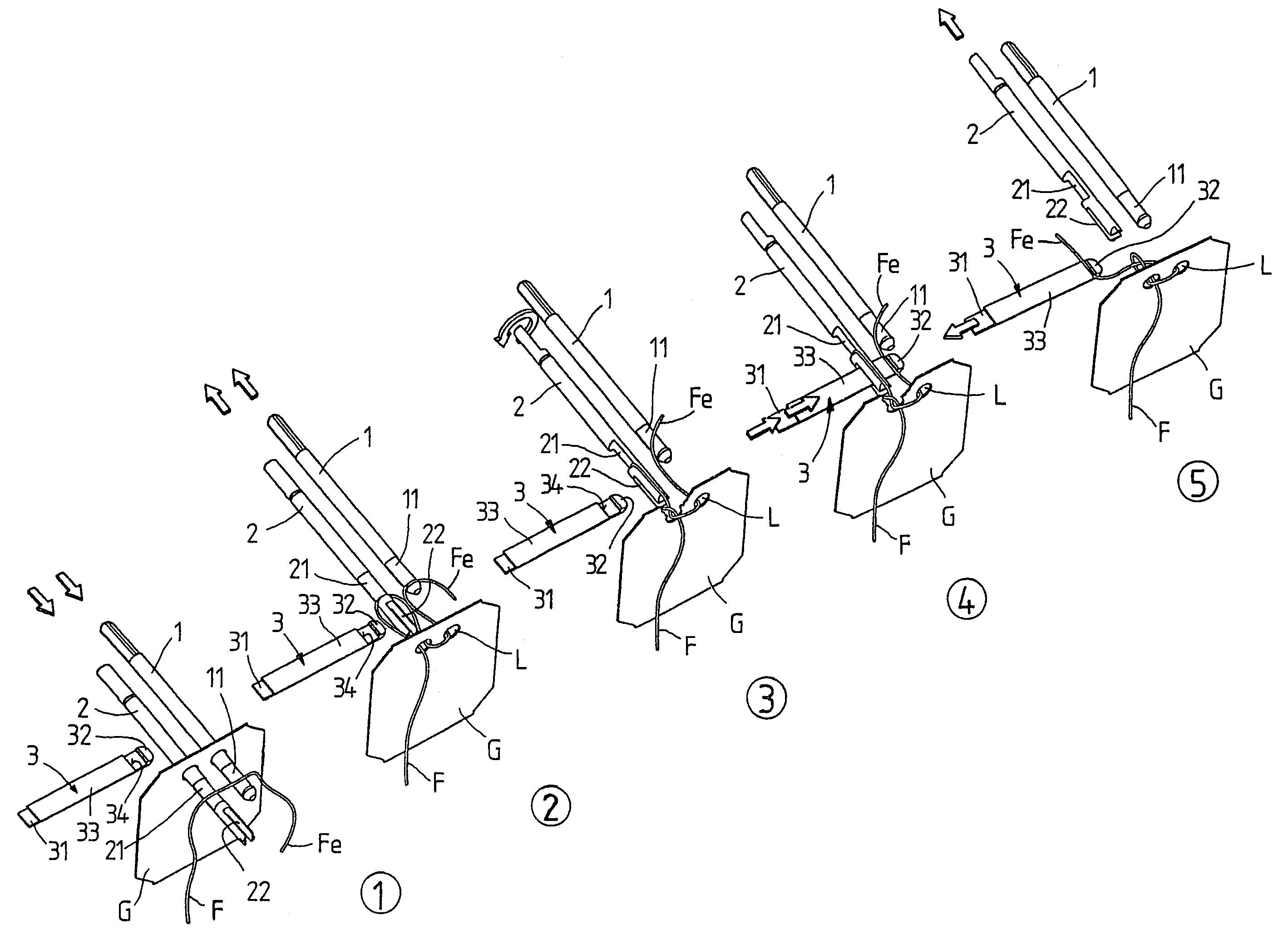
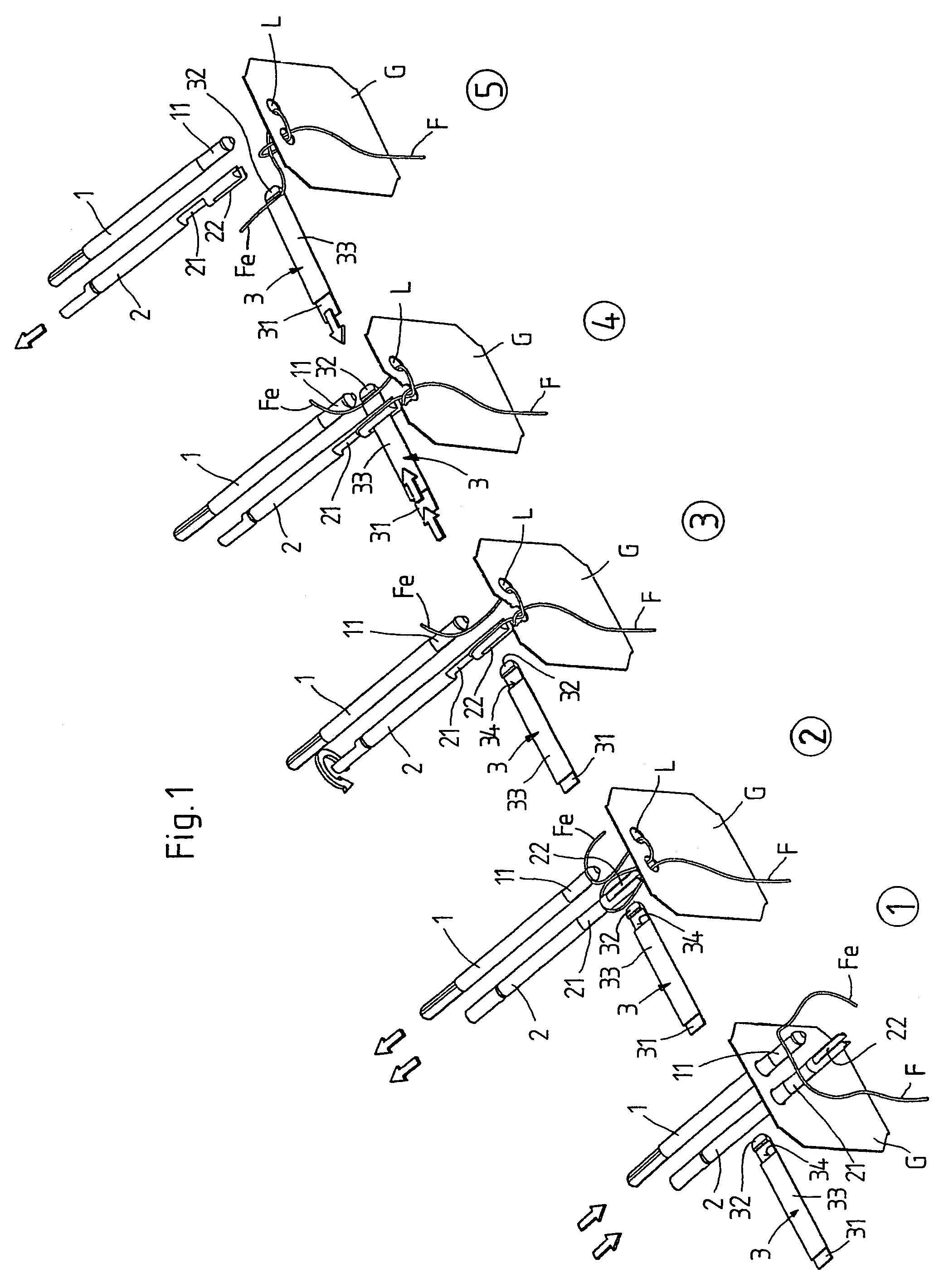
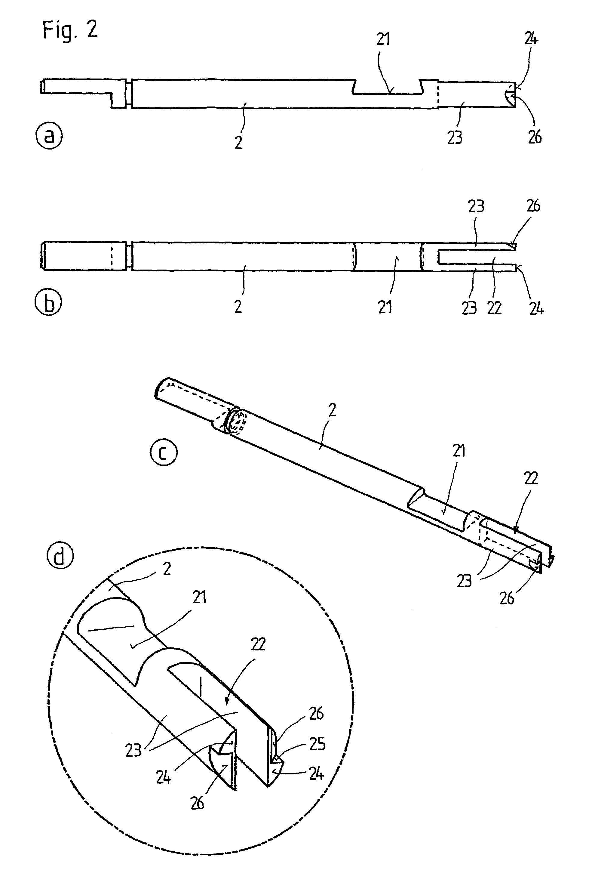
[0020]The device for knotting the end of a thread F to a flat object G, which is depicted in form of a label in FIG. 1, comprises three tools, specifically a first bar 1, a second bar 2 and a gripper 3. These three tools are depicted in five different positions in FIG. 1 in diagrammatic and perspective views. FIG. 2 shows bar 2 in a side view (a), a top view (b), a perspective depiction (c) and a detailed view (d) with respect to its end face construction.

[0021]As FIG. 1 shows, the bars 1 and 2 extend parallel to and at a distance from each other. The gripper 3 is mobile at a right angle to them in the plane in which the bars 1 and 2 are located.

[0022]As FIG. 1 reveals, the bar 1 is mobile between a front end position (see FIG. 1.1) and a rear end position (see FIG. 1.2 to 1.5). It is equipped with a hook-like recess 11 on its front end, which serves to accommodate the thread F.

[0023]The second bar 2 also comprises a recess 21 of this type which forms a hook, which nonetheless is eq...


PUM


Abstract

The invention relates to a method and a device for knotting the end of a thread to a flat object containing two spaced holes for the knot. The method provides the thread located in front of the holes is pulled to the other side of the object while forming loops, and in that the loop is rotated by at least 270°. Subsequently the end of the thread is pulled through this loop and the knot that is formed is tightened. The device provides three tools, specifically two bars and a gripper.

Description

[0001]The invention relates to a method and a device for knotting the end of a thread to a flat object, in particular an infusion bag for preparing beverages and / or a label, containing two spaced holes for the knot.BACKGROUND OF INVENTION[0002]A large number of methods and devices for knotting the end of a thread to a flat object are known. The methods, most of which employ needles, are so complicated that their operating speed is limited. The corresponding devices consist of a large number of parts with a complicated sequence of motions so that they require a relatively large technical expenditure, especially for control of the parts.[0003]The knots that are created with the familiar methods and devices are formed between a hole and an edge of the flat object. The thread forming the knot thus runs in the fiber direction of the paper forming the flat object. If heavy stress is applied to the knot, it can cause the paper to tear, especially when a slot for clamping the thread is prov...

Claims


Application Information

Patent Timeline
Patent Type & Authority Patents(United States)
IPC IPC(8): B65H69/04B65B29/04D03J3/00
CPCB65B29/04
Inventor LAMBERTZ, STEFANHAUERS, MANFREDVITS, DIETER
Owner TEEPACK SPEZIALMASCH
Why Eureka
Try Eureka