

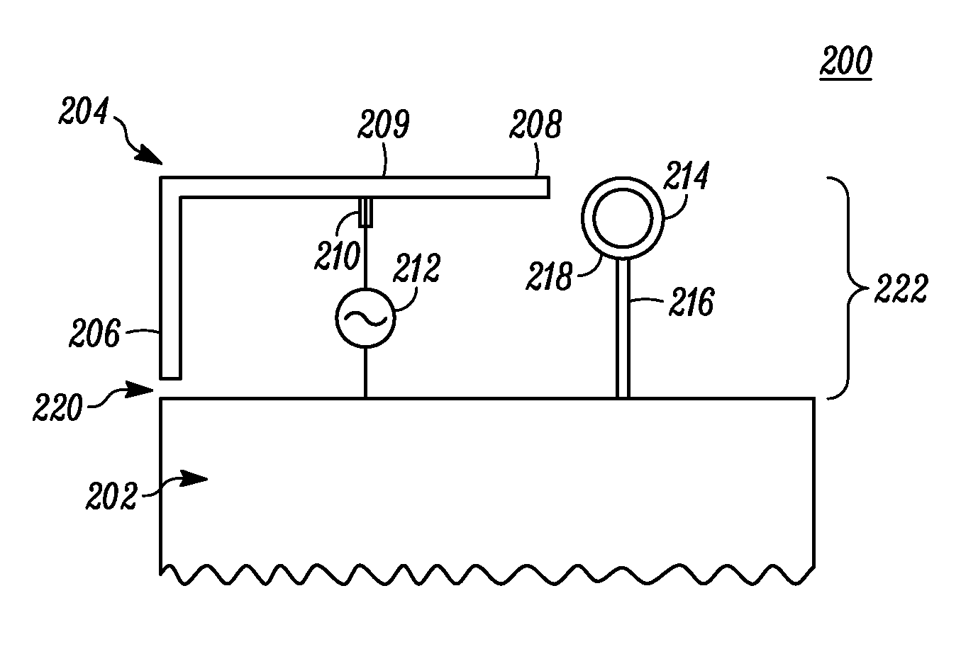
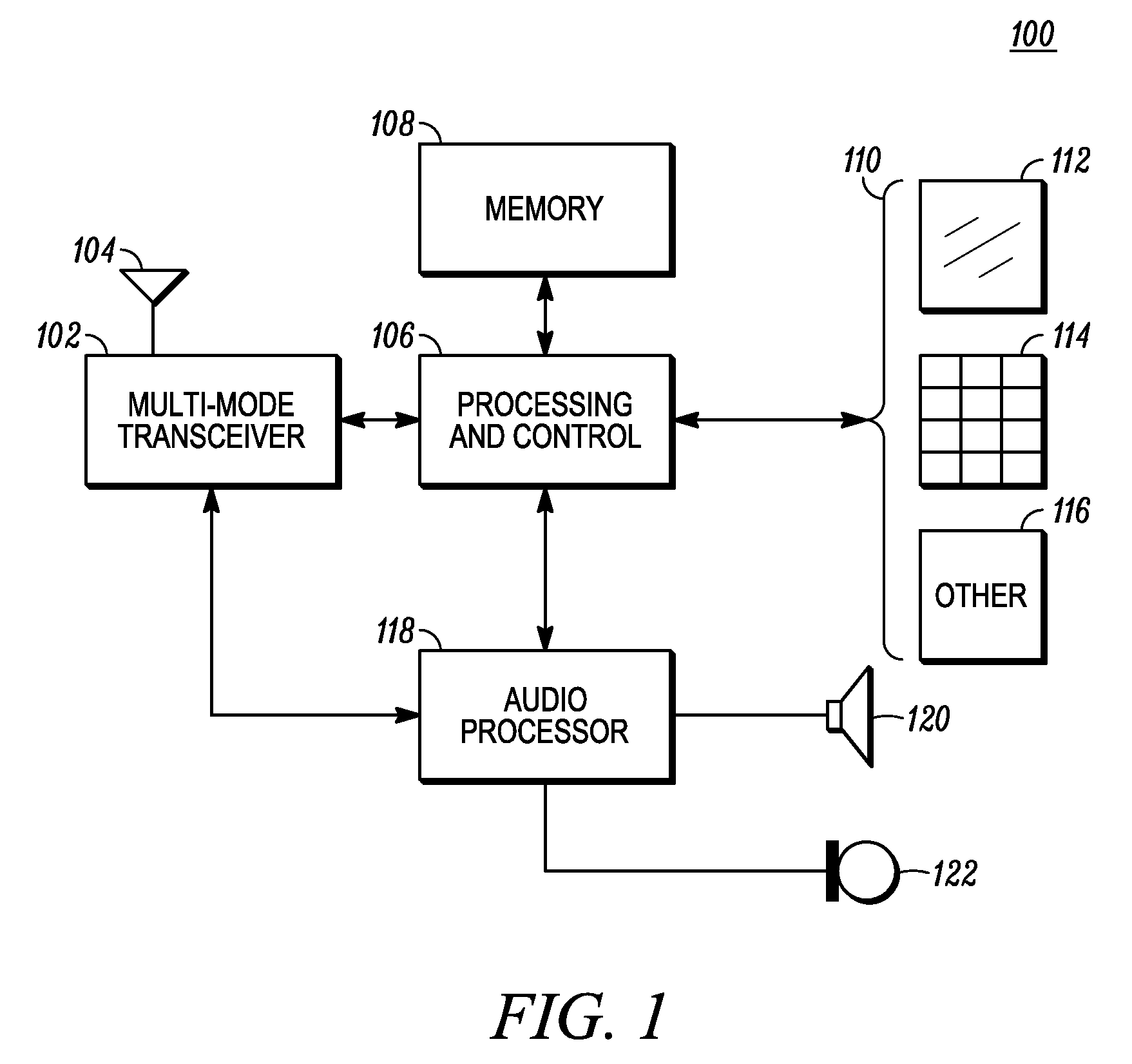
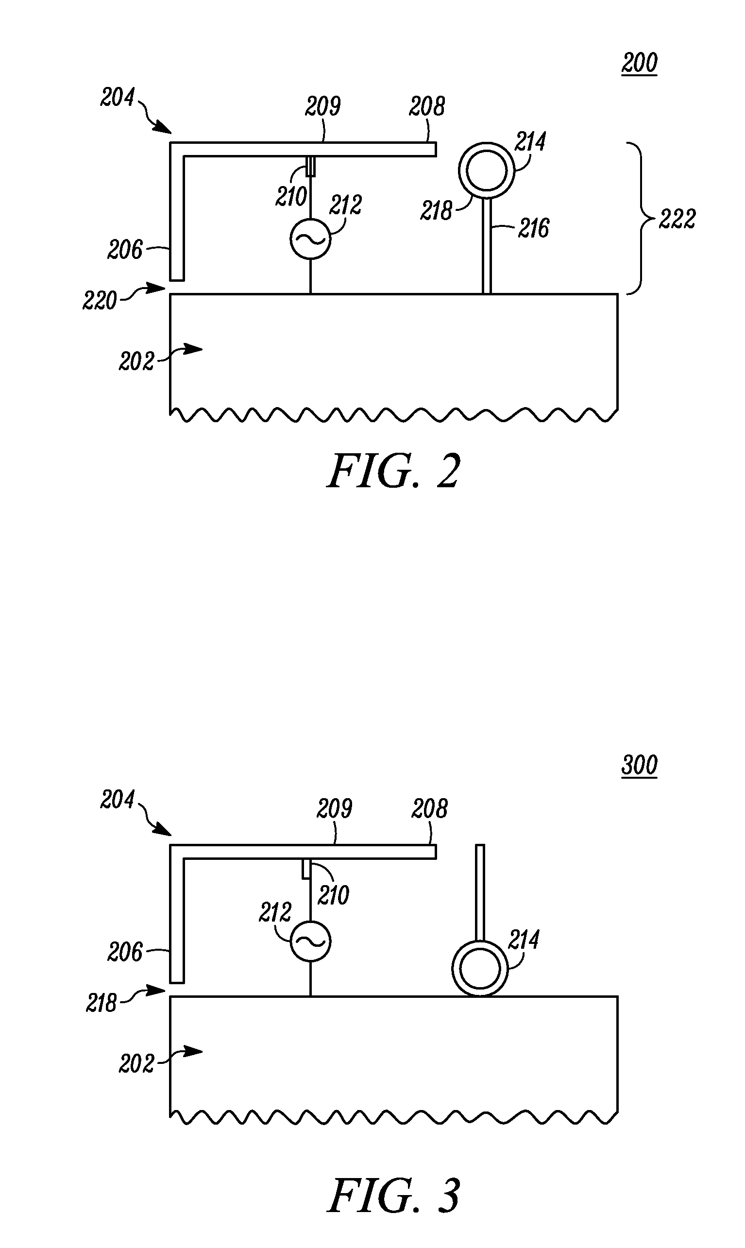
Planar inverted-F antenna with parasitic conductor loop and device using same
a technology of inverted conductor loops and antennas, applied in the field of compact antenna structures, can solve the problems of requiring a substantial amount of mechanical support, not performing well across multiple bands of typical whip antennas
- Summary
- Abstract
- Description
- Claims
- Application Information
AI Technical Summary
Benefits of technology
Problems solved by technology
Method used
Image

Examples
Embodiment Construction
[0012]While the specification concludes with claims defining features of the invention that are regarded as novel, it is believed that the invention will be better understood from a consideration of the description in conjunction with the drawings. As required, detailed embodiments of the present invention are disclosed herein; however, it is to be understood that the disclosed embodiments are merely exemplary of the invention, which can be embodied in various forms. Therefore, specific structural and functional details disclosed herein are not to be interpreted as limiting, but merely as a basis for the claims and as a representative basis for teaching one skilled in the art to variously employ the present invention in virtually any appropriately detailed structure. Further, the terms and phrases used herein are not intended to be limiting but rather to provide an understandable description of the invention.
[0013]Referring now to FIG. 1, there is shown a block schematic diagram of ...
PUM
 Abstract
Description
Claims
Application Information