Low cost flight attachment for modular belts

a modular belt and low-cost technology, applied in the field of conveyor belts, can solve the problems of high cost and manufacturing complexity, no flexibility in the above configuration, and the goods, products, or raw materials on the conveyor may slip down the inclined modular belt, etc., and achieve the effect of low cost and convenient installation

Inactive Publication Date: 2007-09-11
HABASIT AG
View PDF15 Cites 6 Cited by
  • Summary
  • Abstract
  • Description
  • Claims
  • Application Information

AI Technical Summary

Benefits of technology

[0006]The present invention meets the above-described need by providing a low cost flight for a modular belt conveyor. The present invention also allows for fluid and air to flow freely along the belt and is not significantly hindered by the flight from flowing.
[0009]A load member, which can be embodied to have the same or similar dimensions as the pivot rod, is moved through the second bracket openings. The load member can then have a head formed at its ends so that it does not work its way out of the second bracket openings. The load member and brackets thus provide for a low cost flight for the modular belt conveyor. The flights can be installed in the modular belt conveyor at any desired spaced interval from one another.
[0013]Thus, the flight provided for herein is low cost, lightweight, can be mass produced and is relatively easy to install in the modular belt conveyor. In addition, the flight stabilizes the product being transported on the modular belt conveyor as it is moved up and / or down an incline.

Problems solved by technology

A common problem with inclined modular belt conveyors is that the goods, products, or raw materials on the conveyor may slip down the inclined modular belt due to gravity forces.
One of the problems associated with the above configurations is that they involve significant costs and manufacturing complexity.
In addition, none of the above configurations provide for flexibility because a specific module produced as set forth above does not allow the module to be used in other modular conveyor belts.
Thus, a disadvantage of the above is that a different module and flight are required for each belt.

Method used


Image

  • Low cost flight attachment for modular belts
  • Low cost flight attachment for modular belts
  • Low cost flight attachment for modular belts

Examples


Embodiment Construction

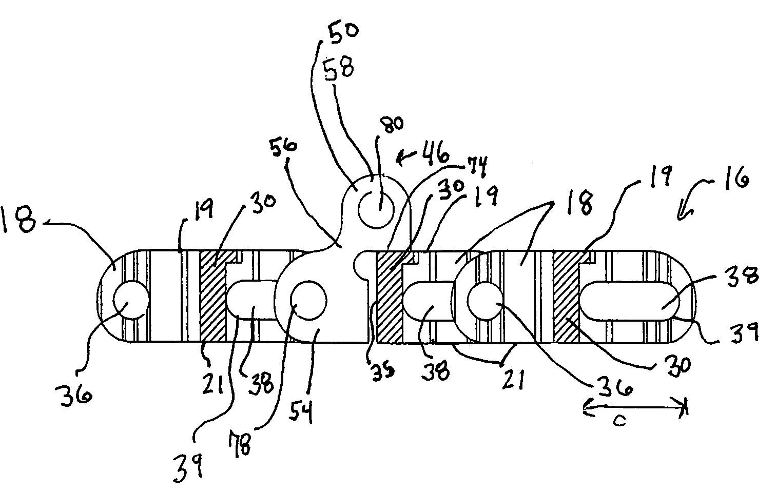
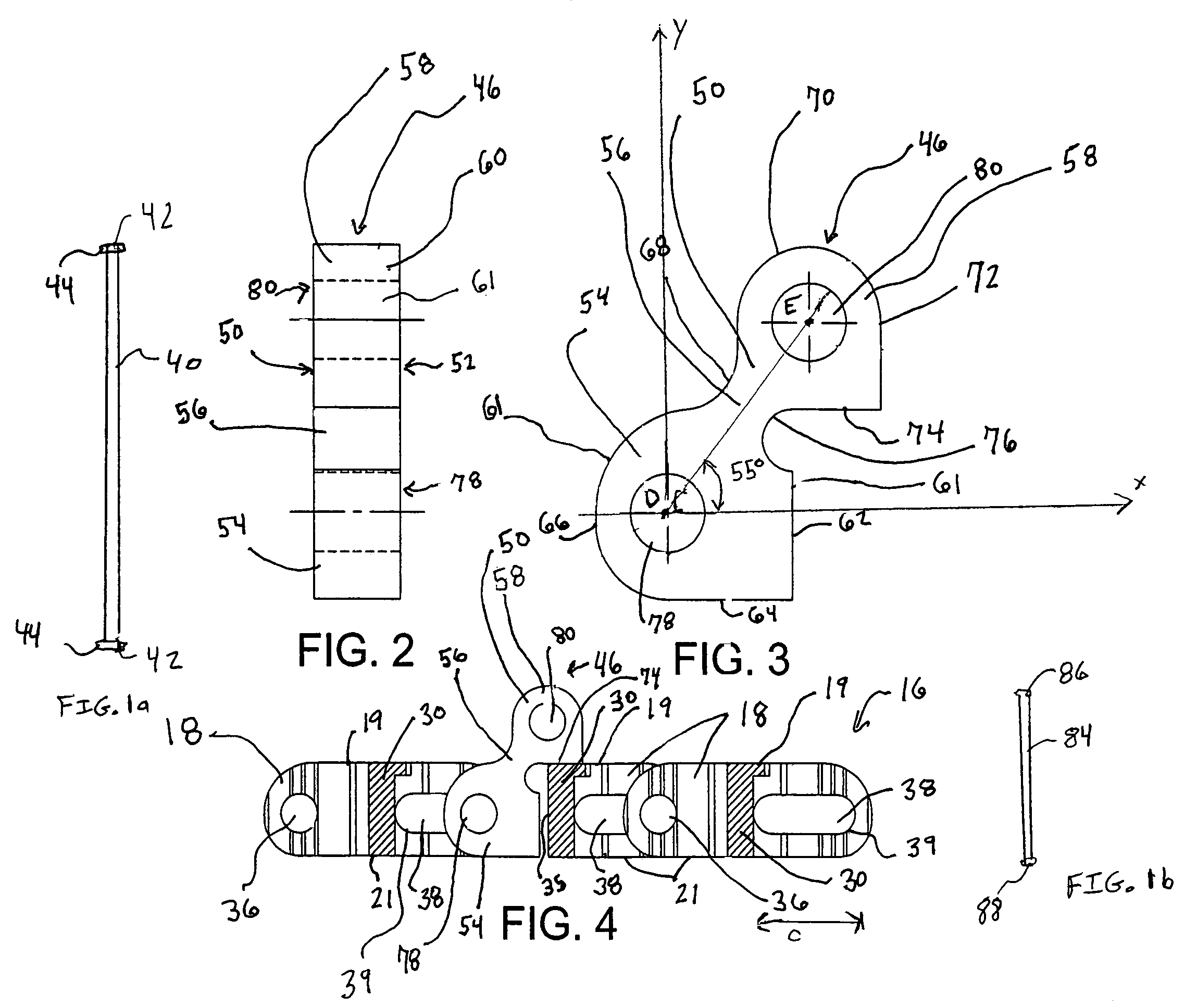
[0027]Referring generally to FIGS. 1-4, flight 45 comprises spaced apart brackets 46 that are attached to a module 18, or row of modules 20, of a modular belt conveyor 16. The brackets 46 support a load member 84 above the row of modules 18 and the load member 84 prevents product being transported on the modular belt conveyor 16 from sliding down an incline due to gravity forces.

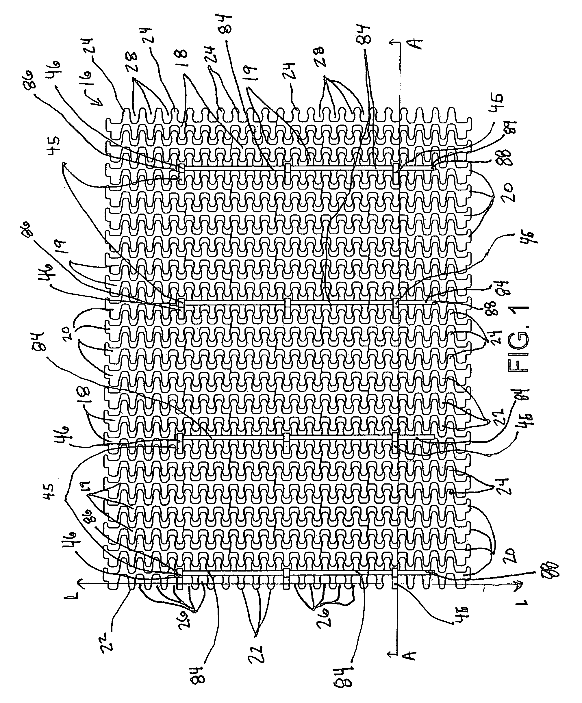
[0028]In particular, FIG. 1 is a top plan view of the modular belt conveyor 16 to which the brackets 46 are attached. The modular belt conveyor 16 comprises modules 18 that are arranged such that they form rows of modules 20. Each module 18 has a load surface 19 upon which the products / goods (not shown) being transported are placed, and an opposed surface 21. The load and opposed surfaces, 19, 21, respectively, are substantially planar. Each module 18 further comprises first link ends 22 that extend in one direction from an intermediate section 30, and second link ends 24 that extend in the opposite directio...


PUM


Abstract

A bracket for use in a modular belt conveyor, the bracket comprises a modular portion having a first bracket opening, a support portion having a second bracket opening, and an offset portion that joins the modular portion and support portion such that the support portion is offset from the modular portion. A pair of spaced apart brackets is installed in a row of modules, and a load member is positioned in the holder openings to make a low cost flight for a modular belt conveyor. A modular link-pair having first and second link ends extending in opposite directions from an intermediate section. The second link end has a holder that has a holder opening, and a pair of modular link-pairs is installed in a row of modules. A load member is positioned in the spaced apart holder openings to thus make a low cost flight.

Description

FIELD OF THE INVENTION[0001]The present invention relates to conveyor belts and more particularly, to modular plastic conveyor belts formed of rows of plastic belt modules pivotally interlinked by transverse pivot rods.BACKGROUND OF THE INVENTION[0002]Modular belt conveyors are used to transport goods, products, and raw materials. Modular belt conveyors are made up of a number of modules that are joined together. These modular belt conveyors can be arranged such that they are horizontal or inclined.[0003]A common problem with inclined modular belt conveyors is that the goods, products, or raw materials on the conveyor may slip down the inclined modular belt due to gravity forces. Examples of past attempts to overcome this problem include the use of flights. These flights are built into the modular belt conveyors in a number of ways. U.S. Pat. No. 4,832,183 to Lapeyre, U.S. Pat. No. 5,413,211 to Faulkner, U.S. Pat. No. 5,490,591 to Faulkner, and U.S. Pat. No. 6,332,531 to Damkjaer sh...

Claims


Application Information

Patent Timeline
Patent Type & Authority Patents(United States)
IPC IPC(8): B65G17/06
CPCB65G17/40B65G17/46B65G2207/30
Inventor MONTEMARTINI, PAOLOMADONINI, ROBERTOVISCONTI, ENRICOFLAVIO, VERBENA
Owner HABASIT AG
Why Eureka
Try Eureka