Method for manufacturing pressure sensor

a manufacturing method and pressure sensor technology, applied in the direction of instruments, semiconductor devices, measurement devices, etc., can solve the problems of corrosion, increased number of components, complicated structure of pressure sensors, etc., and achieve the effect of improving sealing performance between them

Inactive Publication Date: 2007-09-11
DENSO CORP
View PDF3 Cites 6 Cited by
  • Summary
  • Abstract
  • Description
  • Claims
  • Application Information

AI Technical Summary

Benefits of technology

[0009]In view of the above-described problem, it is an object of the present invention to provide a manufacturing method of a pressure sensor with high sealing performance.
[0011]In the above method, the part of the second metal film on the second protection film is easily removed; and therefore, the other part of the second metal film adheres tightly on the first metal film and the first protection film so that sealing performance between the second metal film and the first metal film or the first protection film becomes higher. Thus, the sealing performance therebetween is improved; and therefore, corrosion medium is prevented from penetrating through an interface between the second metal film and the first protection film. Accordingly, no erosion occurs at a pad side.
[0012]Preferably, the step of performing the reduction treatment provides to increase adhesive force between the second metal film and the pad region of the first metal film or the part of the first protection film disposed around the pad region.
[0014]Preferably, the first metal film has a surface protrusion, a height of which is equal to or smaller than 0.5 μm. More preferably, the first metal film includes a titanium film and an aluminum based film. The step of forming the first metal film includes steps of: forming the titanium film; and forming the aluminum based film on the titanium film. The height of the surface protrusion is reduced by orientation of the titanium film. More preferably, the first metal film includes an aluminum-silicon-copper alloy film, and the height of the surface protrusion is reduced by thermal stability of the aluminum-silicon-copper alloy film.
[0016]In the above method, the part of the second metal film adheres tightly on the first metal film and the first protection film so that sealing performance between the second metal film and the first metal film or the first protection film becomes higher. Thus, the sealing performance therebetween is improved; and therefore, corrosion medium is prevented from penetrating through an interface between the second metal film and the first protection film. Accordingly, no erosion occurs at a pad side.

Problems solved by technology

In the case of the pressure sensor having such a configuration, there are problems that the number of components is increased because the metal diaphragm is necessary, and a structure of the pressure sensor is complicated because a structure for sealing the oil using the metal diaphragm is necessary.
However, when such a structure is used, when the pressure sensor is used in a situation where the sensor element comprising semiconductor is exposed to a corrosive liquid, for example, the pressure sensor is used for measurement of differential pressure of DPF that is an exhaust cleaning filer of diesel-powered automobiles or pressure measurement in an atmosphere within an engine room, a problem that corrosion occurs because material of a bonding pad is Al.
However, even if the above structure is used, it has been newly found that since adhesion between the protection film comprising SiN formed in the periphery of the pad and the Au film is not good, the corrosion medium that has penetrated through the gel protection layer through an interface between the Au film and the protection film enters a pad side, and therefore, the corrosion medium causes erosion.

Method used


Image

  • Method for manufacturing pressure sensor
  • Method for manufacturing pressure sensor
  • Method for manufacturing pressure sensor

Examples


first embodiment

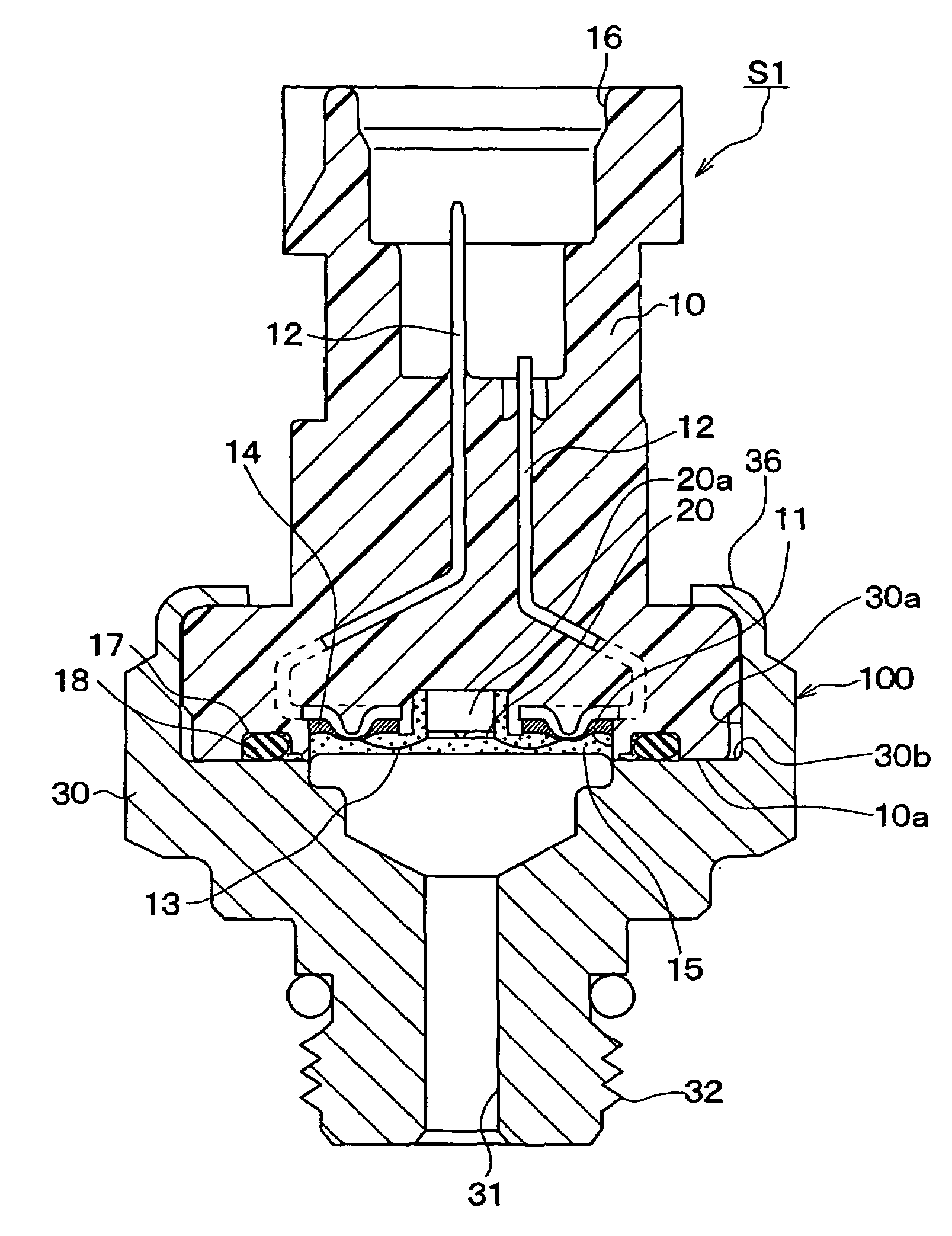
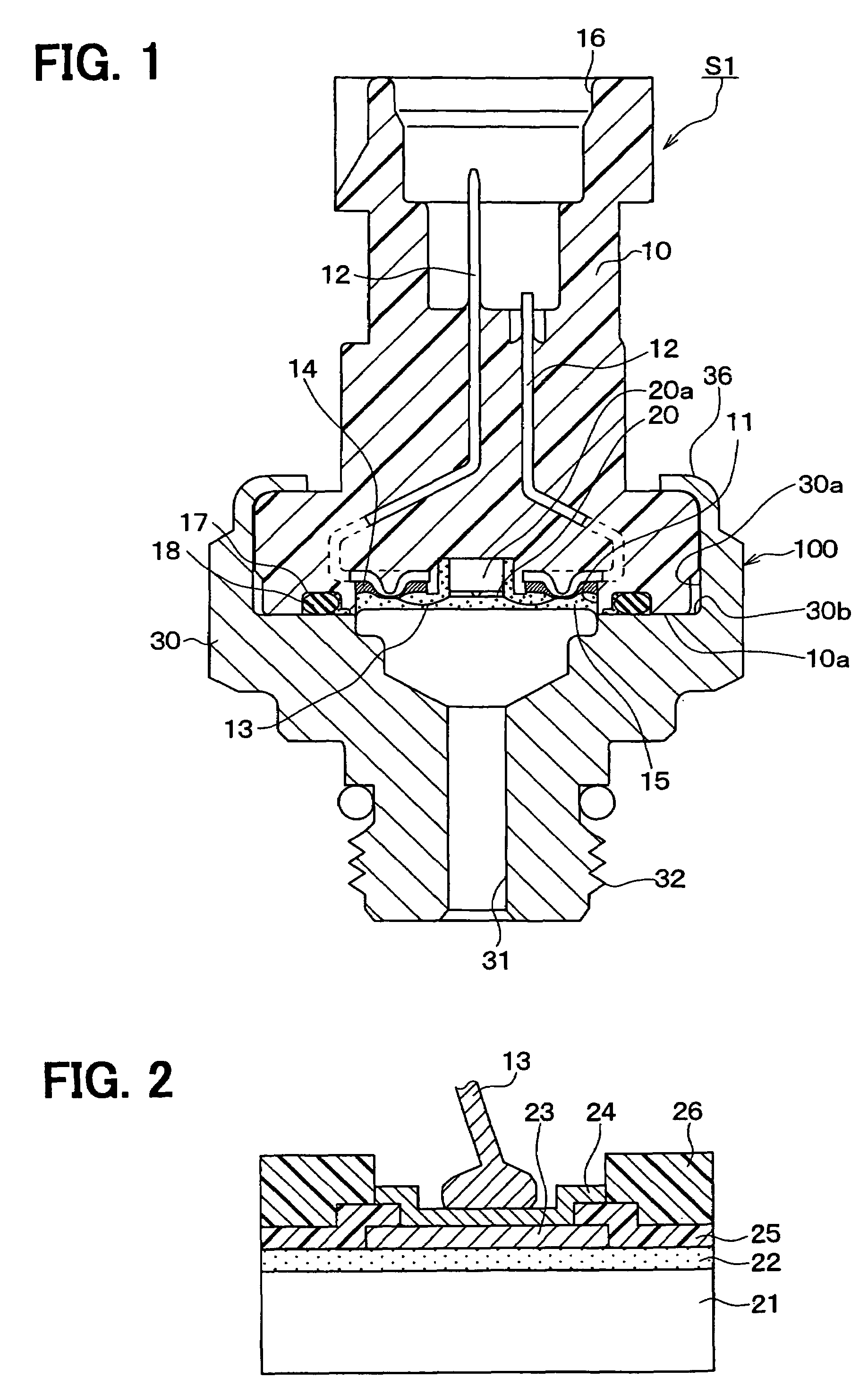
[0025]Hereinafter, a pressure sensor to which an embodiment of the invention is applied will be described. FIG. 1 is a cross section drawing of a pressure sensor S1 in the embodiment, and description is made according to the drawing. The pressure sensor S1 is, for example, used for differential pressure measurement of DPF that is an exhaust cleaning filter of diesel-powered automobiles.

[0026]As shown in FIG. 1, a connector case 10 as a first case is produced by die forming of resin such as PPS (poly phenylene sulfide) or PBT (poly butylene terephthalate) and formed in an approximately cylindrical shape in the embodiment. A recess 11 is formed at one end portion (end portion at a lower side in FIG. 1) of the connector case 10 as the resin case.

[0027]A sensor element 20 for pressure detection is set on a bottom of the recess 11.

[0028]The sensor element 20 is an element of a semiconductor diaphragm type, in which a diaphragm as a pressure receiving surface is provided. Pressure receive...

second embodiment

[0063]A second embodiment of the invention is described. While the case that the Al film 23 is used as the first metal film was described in the first embodiment, when the Al film 23 is used, self diffusion of atoms may occur at grain boundaries due to heat treatment after forming the Al film 23, which sometimes causes gathering of the atoms in the surface of the Al film 23 and formation of a protrusion called hillock (hereinafter, referred to as hillock) 23a. Height of the hillock 23a as a surface protrusion of the aluminum film 23 sometimes reaches 2 μm to 3 μm.

[0064]When the height of the hillock 23a is increased, a problem may occur as shown in a cross section drawing of a connection structure shown in FIG. 4A: the hillock 23a reduces covering performance of a film including the Au film that is the second metal film, therefore the Al film 23 can not be protected from a corrosive atmosphere in the corrosive atmosphere, consequently a portion that has not been sufficiently covered...

third embodiment

[0069]A third embodiment of the invention is described. The invention is to reduce the height of the hillock 23a formed in the Al film 23, as in the case of the second embodiment.

[0070]FIG. 6 is a cross section drawing of an electrical connection structure in a bonding portion between a sensor element and a bonding wire in a pressure sensor of the embodiment. The embodiment is an embodiment in which the electrical connection structure in the bonding portion is changed from that in the first embodiment, but a basic structure of the pressure sensor is same as in the first embodiment, therefore only different portions from the first embodiment are described.

[0071]In a connection structure shown in FIG. 6, the Al film 23 is changed from a pure Al film to an alloy film containing Al as a main component such as Al—Si—Cu. Specifically, the Al film 23 is configured by using an alloy of Al—Si—Cu containing Al as a main component, Si of 0.01% to 4% (for example, 0.4%), and Cu of 0.01% to 5% (...


PUM


Abstract

A method for manufacturing a pressure sensor includes the steps of: preparing a semiconductor substrate; forming an insulation film on the substrate; forming a first metal film on the insulation film; forming a first protection film on the first metal film and the insulation film; forming a second protection film on the first metal film and the first protection film; performing reduction treatment of adhesive force on the second protection film, the force between the second protection film and a second metal film; forming the second metal film on the first metal film and the first protection film; and removing a part of the second metal film.

Description

CROSS REFERENCE TO RELATED APPLICATIONS[0001]This application is based on Japanese Patent Applications No. 2005-10340 filed on Jan. 18, 2005, and No. 2005-300299 filed on Oct. 14, 2005, the disclosures of which are incorporated herein by reference.FIELD OF THE INVENTION[0002]The present invention relates to a method for manufacturing a pressure sensor.BACKGROUND OF THE INVENTION[0003]There has been proposed a structure in which a sensor element comprising semiconductor and a bonding portion that is electrically connected to a pad provided on the sensor element. The sensor element and the bonding portion are covered with a metal diaphragm into which oil is filled. This is disclosed in, for example, JP-A-H7-243926, which corresponds to U.S. Pat. No. 5,595,939.[0004]In a pressure sensor having such a structure, once a fluid as a pressure medium is introduced through a pressure introduction hole provided in the pressure sensor, pressure of the fluid is applied to the sensor element via ...

Claims


Application Information

Patent Timeline
Patent Type & Authority Patents(United States)
IPC IPC(8): H01L21/00
CPCG01L9/0042H01L2224/48463H01L2224/45144H01L2924/00
Inventor TOMISAKA, MANABUWATANABE, YOSHIFUMITANAKA, HIROAKI
Owner DENSO CORP
Why Eureka
Try Eureka