Signal processing circuit for tuner which applies signal processing based on variation in frequency of intermediate frequency signal

a signal processing circuit and intermediate frequency signal technology, applied in the direction of signal processing circuits, brightness and chrominance, electrial characteristics varying frequency control, etc., can solve the problems of increasing the cost, increasing the degradation of the sn ratio and affecting the accuracy of adjacent interference detection, so as to inhibit the degradation of the sound quality of the demodulated signal

Active Publication Date: 2007-09-11
SEMICON COMPONENTS IND LLC
View PDF5 Cites 4 Cited by
  • Summary
  • Abstract
  • Description
  • Claims
  • Application Information

AI Technical Summary

Benefits of technology

[0015]An advantage of the present invention is that, in a signal processing circuit for a tuner, a variation in a carrier frequency of an intermediate frequency signal input from a tuner is detected and a frequency filter for signal processing can be suitably controlled based on an amount of the variation.
[0016]According to one aspect of the present invention, there is provided a signal processing circuit for a tuner which receives an input of an intermediate frequency (IF) signal produced by mixing a received broadcasting signal and a local oscillator frequency signal produce by a first local oscillator and detects and demodulates the IF signal, the signal processing circuit comprising a signal detector, which operates based on a clock signal produced by a second local oscillator, for detecting the intermediate frequency signal; and a frequency variation detector for detecting a difference in frequency between a carrier of the IF signal and the clock signal and for outputting the IF variation signal, wherein the frequency variation detector comprises a detector band pass filter (BPF) for extracting a carrier of the IF signal, a frequency counter for counting, based on the clock signal, a frequency of the carrier of the IF signal which is passed through the detector BPF, and an IF variation signal outputting section for outputting an IF variation signal based on a difference between the counted frequency and a frequency of the clock signal, and a frequency selection characteristic in an operation of the signal processing circuit for a tuner is controlled based on the IF variation signal.
[0017]With this structure, even when the carrier frequency of the IF signal varies, the frequency selection characteristic of the frequency filter in the signal processing circuit for a tuner can be optimally controlled according to the amount of variation, and it is possible to inhibit degradation of sound quality of the demodulated signal.

Problems solved by technology

In this configuration, because provision of two types of different clock frequencies would increase the cost, the signal processing circuit for the tuner also is required to operate with a common reference clock frequency.
In a detection process in a signal processing circuit for a tuner, the variation of carrier frequency of an input intermediate frequency signal with respect to a clock frequency of the signal processing circuit for a tuner can cause increase in degradation of SN ratio of the demodulated signal and degradation of adjacent interference detection precision.

Method used


Image

  • Signal processing circuit for tuner which applies signal processing based on variation in frequency of intermediate frequency signal
  • Signal processing circuit for tuner which applies signal processing based on variation in frequency of intermediate frequency signal
  • Signal processing circuit for tuner which applies signal processing based on variation in frequency of intermediate frequency signal

Examples


Embodiment Construction

[0021]A preferred embodiment of the present invention will now be described referring to the drawings.

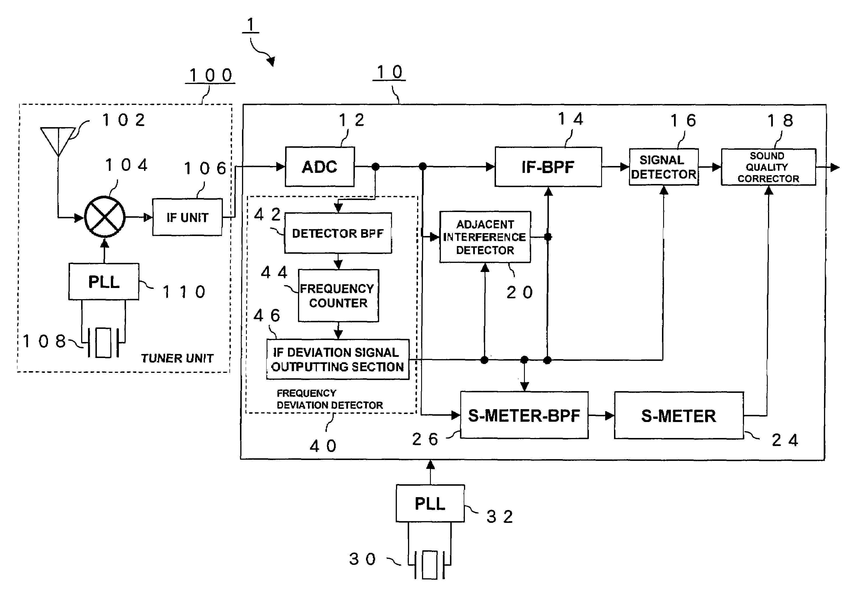
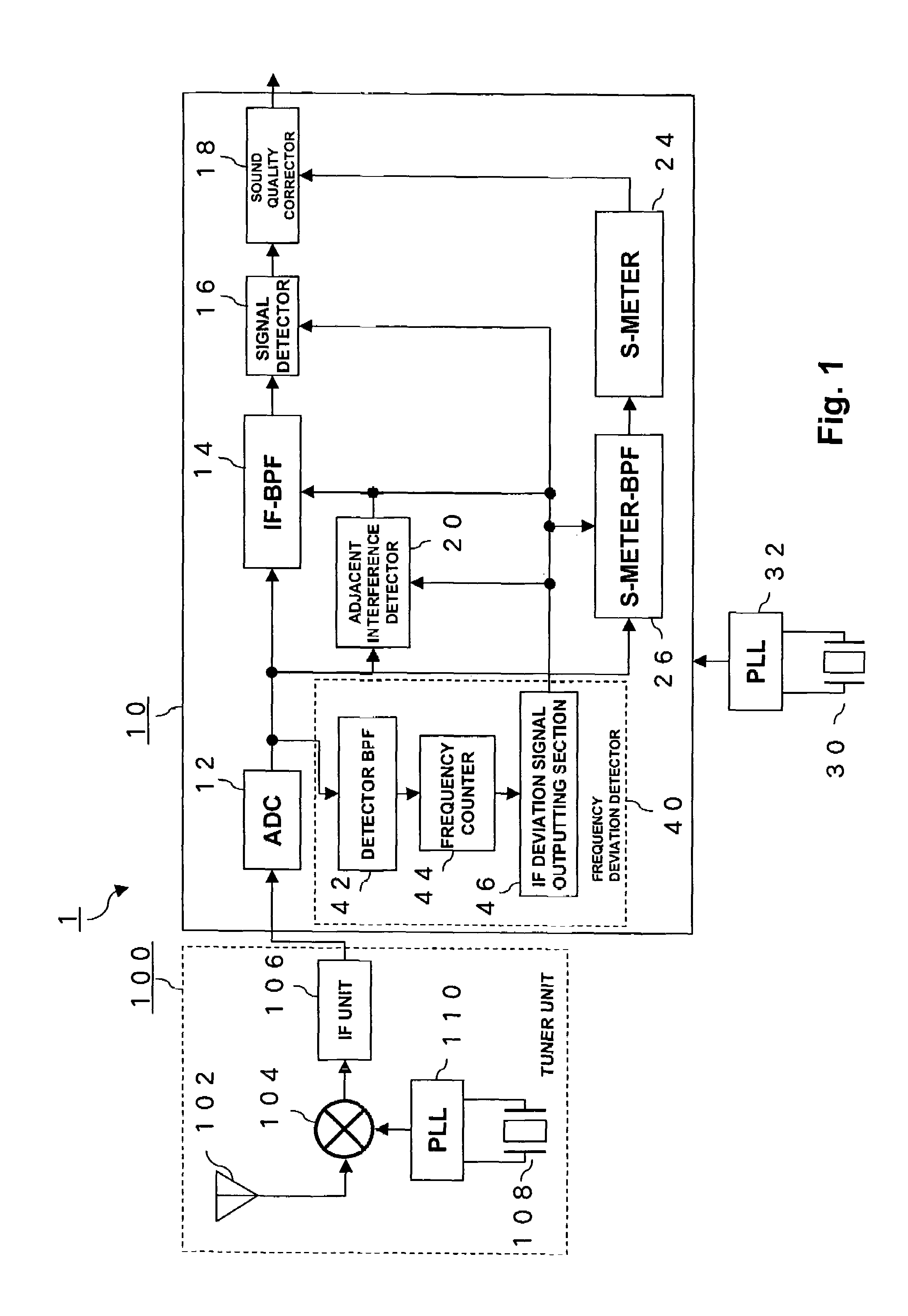
[0022]FIG. 1 is a diagram showing a structure of an AM receiver circuit 1 including a signal processing circuit for a tuner according to a preferred embodiment of the present invention.

[0023]An AM receiver circuit 1 can be primarily separated into two sections including a tuner unit 100 for receiving a broadcasting radio wave and outputting an intermediate frequency (IF) signal, and a tuner digital signal processor (DSP) 10 which is a signal processing circuit for a tuner which receives the IF signal.

[0024]The tuner unit 100 comprises an antenna 102 for receiving broadcast radio waves, a mixer 104 for converting a broadcast signal of a desired station into an intermediate frequency (IF) signal having a carrier frequency of 450 kHz, and an IF unit 106 for amplifying an IF signal output from the mixer 104. A local oscillator signal from a local oscillator which allows tuning to an osc...


PUM


Abstract

A signal processing circuit for a tuner has a detector band pass filter for extracting a carrier of an intermediate frequency signal, a frequency counter for counting, based on a clock signal, a frequency of a carrier of the intermediate frequency signal which passes through the detector band pass filter, and an intermediate frequency variation signal outputting section for outputting an intermediate frequency variation signal based on a difference between the counted frequency and a frequency of the clock signal. Based on the intermediate frequency variation signal, a frequency selection characteristic of an intermediate frequency band pass filter, a signal detector, an adjacent interference detector, or an S-meter-band pass filter are controlled. In this manner, even when a carrier frequency of an intermediate frequency signal input from a tuner varies, the frequency selection characteristic of the intermediate frequency band pass filter, signal detector, adjacent interference detector, and S-meter-band pass filter can be suitably controlled.

Description

CROSS-REFERENCE TO RELATED APPLICATIONS[0001]The priority Japanese Patent Application Number 2003-304953 upon which this patent application is based is hereby incorporated by reference.BACKGROUND OF THE INVENTION[0002]1. Field of the Invention[0003]The present invention relates to a signal processing circuit for a tuner, and in particular to a signal processing circuit for a tuner which applies signal processing based on a frequency variation when a carrier frequency of an input intermediate frequency (“IF”) signal is varied.[0004]2. Description of the Related Art[0005]An AM (amplitude modulation) system is used for transmitting a signal to be transmitted (modulating signal) on an amplitude of a signal (carrier) having a frequency which can be radiated from a broadcasting station and is primarily used in medium frequency radio broadcasting (526.5 kHz–1606.5 kHz). Radio waves in a medium frequency radio broadcasting frequency band have a characteristic that a wide service area can be...

Claims


Application Information

Patent Timeline
Patent Type & Authority Patents(United States)
IPC IPC(8): H04B1/06H04B7/00H04B1/26H03J7/04H04B1/10H04B1/16H04B1/18H04L27/02H04N9/77H04N9/79H04N17/00
CPCH03J7/045H04B1/10H04L27/02
Inventor SAITO, YASUJITAIRA, MASAAKIHIRAKOSO, YUTAKA
Owner SEMICON COMPONENTS IND LLC
Why Eureka
Try Eureka