Light sensing circuit, backlight control apparatus having the same, and liquid crystal display device having the same

a technology of backlight control and light sensing circuit, which is applied in the direction of static indicating devices, non-linear optics, instruments, etc., can solve problems such as power was

Active Publication Date: 2007-12-27
LG DISPLAY CO LTD
View PDF18 Cites 2 Cited by
  • Summary
  • Abstract
  • Description
  • Claims
  • Application Information

AI Technical Summary

Benefits of technology

[0020]A backlight control apparatus for controlling a backlight to irradiate light to a rear side of an LC panel, the apparatus includes a light sensing circuit for detecting an amount of external light introduced into the LC panel by a first MOS-transistor and a second MOS-transistor serially connected to each other, and outputting a voltage corresponding to the optical amount according to the detected optical amount; an inverter for supplying an output power to the backlight; and an inverter driving controller for controlling a driving of the inverter according to the detected voltage from the light sensing circuit.

Problems solved by technology

However, the conventional backlight has been constructed so as to maintain a brightness constant regardless of a peripheral brightness, thereby wasting power.

Method used


Image

  • Light sensing circuit, backlight control apparatus having the same, and liquid crystal display device having the same
  • Light sensing circuit, backlight control apparatus having the same, and liquid crystal display device having the same
  • Light sensing circuit, backlight control apparatus having the same, and liquid crystal display device having the same

Examples


Embodiment Construction

[0028]Reference will now be made in detail to the preferred embodiments of the present invention, examples of which are illustrated in the accompanying drawings.

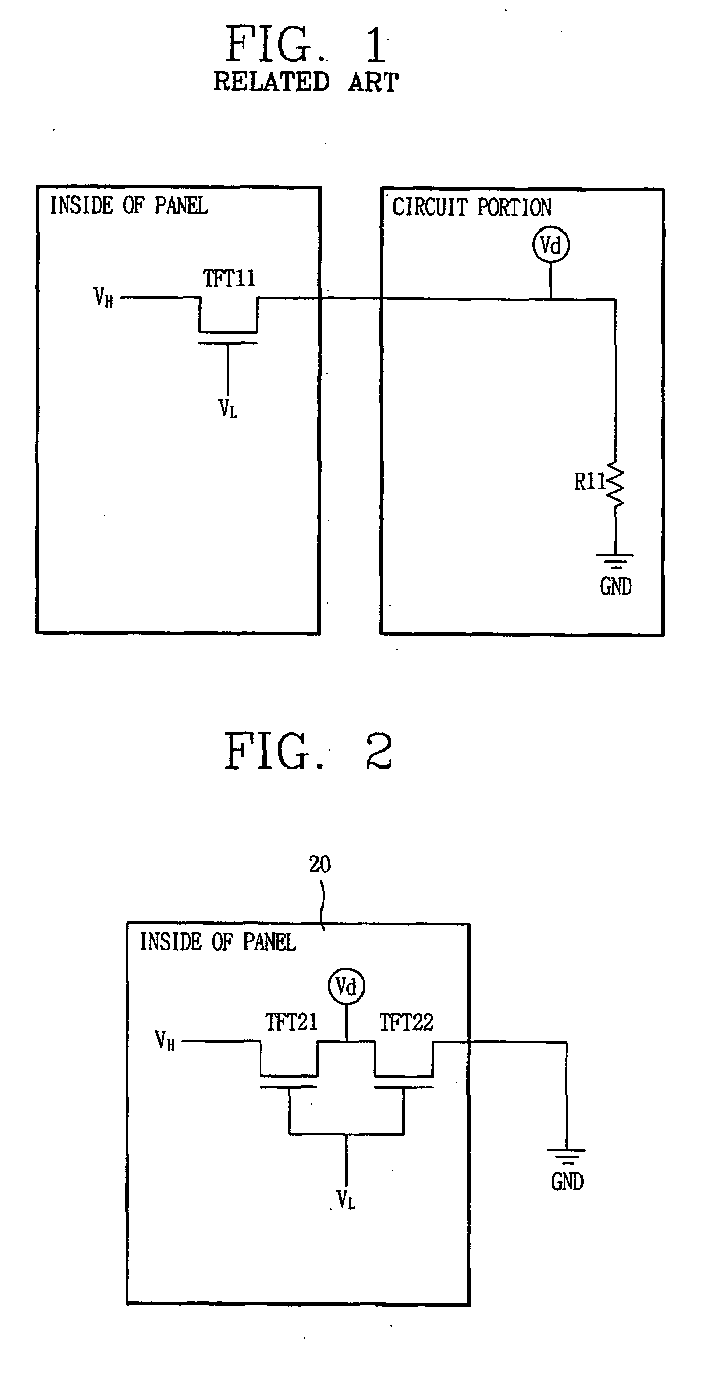
[0029]FIG. 2 is a circuit diagram showing a light sensing circuit for an LCD device. As shown, a light sensing circuit 20 comprises a first MOS-transistor and a second MOS-transistor serially connected to each other between a first power terminal (VH) and a ground terminal (GND), in which a second power terminal (VL) is connected to each gate terminal of the first MOS-transistor and the second MOS-transistor, and an optical amount detecting terminal (Vd) is connected to a common connection point between a drain terminal of the first MOS-transistor and a source terminal of the second MOS-transistor.

[0030]The light sensing circuit 20 will be explained in more detail with reference to FIGS. 2 and 3.

[0031]As shown in FIG. 2, in the light sensing circuit 20, an amorphous-silicon type (a-Si) first MOS-transistor TFT21 is connected...


PUM


Abstract

A light sensing circuit capable of enhancing a reliability by lowering a dependency on a temperature change without using a resistor, a backlight control apparatus having the same, and an LCD device having the same. The light sensing circuit includes a first MOS-transistor; and a second MOS-transistor serially connected to the first MOS-transistor between a first power terminal and a ground terminal, in which a second power terminal is connected to each gate terminal of the first MOS-transistor and the second MOS-transistor, and an optical amount detecting terminal is connected to a common connection point between a drain terminal of the first MOS-transistor and a source terminal of the second MOS-transistor.

Description

RELATED APPLICATION[0001]The present disclosure claims the benefit of priority of Korean Application No. 10-2006-057131, filed on Jun. 23, 2006, which is herein expressly incorporated by reference in its entirety.BACKGROUND[0002]1. Technical Field[0003]The present invention relates to a light sensing circuit capable of measuring an optical amount, a backlight control apparatus having the same, and a liquid crystal display (LCD) device having the same, and more particularly, to a light sensing circuit capable of lowering a dependency on a temperature change without using a resistor, a backlight control apparatus having the same, and an LCD device having the same.[0004]2. Description of the Related Art[0005]Generally, an LCD device serves to display a desired image by controlling an amount of light that passes through a liquid crystal layer by controlling an arrangement of a liquid crystal molecule having a refractivity anisotropy using an electric field.[0006]The LCD device consists ...

Claims


Application Information

Patent Timeline
Patent Type & Authority Applications(United States)
IPC IPC(8): G09G3/36
CPCG09G3/3406G09G2360/144G09G2330/021G09G2320/0626G02F1/133
Inventor YOON, JEONG-WONMOON, SU-HWAN
Owner LG DISPLAY CO LTD
Why Eureka
Try Eureka