Clamshell portable wireless terminal with an upper housing and a lower housing joined together with a rotating hinge

a portable wireless terminal and hinge technology, applied in the field of compact hinge apparatus, can solve the problems of large hinge portion size, large apparatus size, and risk of cutting out the conductor portion (circuit pattern) of flexible printed board

Inactive Publication Date: 2007-09-18
PANASONIC CORP
View PDF7 Cites 45 Cited by
  • Summary
  • Abstract
  • Description
  • Claims
  • Application Information

AI Technical Summary

Benefits of technology

[0014]As a consequence, since the cover members are pivotably moved at the same time in connection with the rotating movement of the first rotating shaft, the cover members can be continuously made in close contact to the first rotating shaft. As a result, since no clearance is produced between the first rotating shaft and the cover members when the casing member is pivotably moved while the first rotating shaft is set as the shaft, it is possible to avoid that rain and the like are penetrated.
[0015]Also, an opening / closing type communication terminal, according to the present invention, is featured by that a rotating movement restricting member is provided in a hollow-shaped internal portion of the first rotating shaft; and the rotating movement restricting member restricts both the rotating movement while the first rotating shaft is set as the axis and the rotating movement while the second rotating shaft is set as the axis. As a consequence, since the rotation radius while the first rotating shaft is set as the axis can be made small, the hinge portion can be made compact.
[0018]As a consequence, even when the user mistakenly operates the communication terminal, it is possible to avoid that one casing member is struck and scratched by the other casing member.
[0020]As previously explained, since the head portion of the fastening screw is hidden under the folded condition and the fist opened condition, an outer appearance of the communication terminal can be improved. Also, since the head portion of the fastening screw is exposed under such a condition defined from the first opened condition up to the second opened condition, the cover members can be easily dismounted from the first rotating shaft.
[0022]As a consequence, a user who holds this communication terminal by his hand can confirm the image by viewing the inverted mirror image displayed on the second display unit. On the other hand, a person corresponding to a photographic object located in front of the user can confirm how the own image is photographed by viewing the mirror image displayed on the first display unit.

Problems solved by technology

However, in the above-explained conventional communication terminal, even if the conventional hinge portion is mounted on such an apparatus as a portable telephone which is requested to be made compact so as to realize an opening / closing type portable telephone and the like, there is a problem that the apparatus becomes a large size due to the dimension of the hinge portion.
There is such a problem that the size of the hinge portion becomes large.
Furthermore, since the opening / closing type portable telephone, or the like owns such a structure that bending stress and twist stress are produced on the flexible printed board in connection with the opening / closing operation thereof, there is a risk that a conductor portion (circuit pattern) of the flexible printed board is cut out.
However, when various sorts of stress are applied in a composite manner to the flexible printed board, circuit disconnections and broken boards of the flexible printed board may be conducted.
There is a risk that rain and the like are entered into this clearance, which may cause corrosion of appliances.

Method used


Image

  • Clamshell portable wireless terminal with an upper housing and a lower housing joined together with a rotating hinge
  • Clamshell portable wireless terminal with an upper housing and a lower housing joined together with a rotating hinge
  • Clamshell portable wireless terminal with an upper housing and a lower housing joined together with a rotating hinge

Examples


Embodiment Construction

[0037]Referring now to drawings, a detailed description is made of an embodiment as to opening / closing type communication terminal according to the present invention. It should be understood that although the communication terminal will be described as an opening / closing type portable telephone in this embodiment, the present invention is not limited only to portable telephones, but the present invention may be applied to any other apparatus if these other apparatus are opening / closing type apparatus.

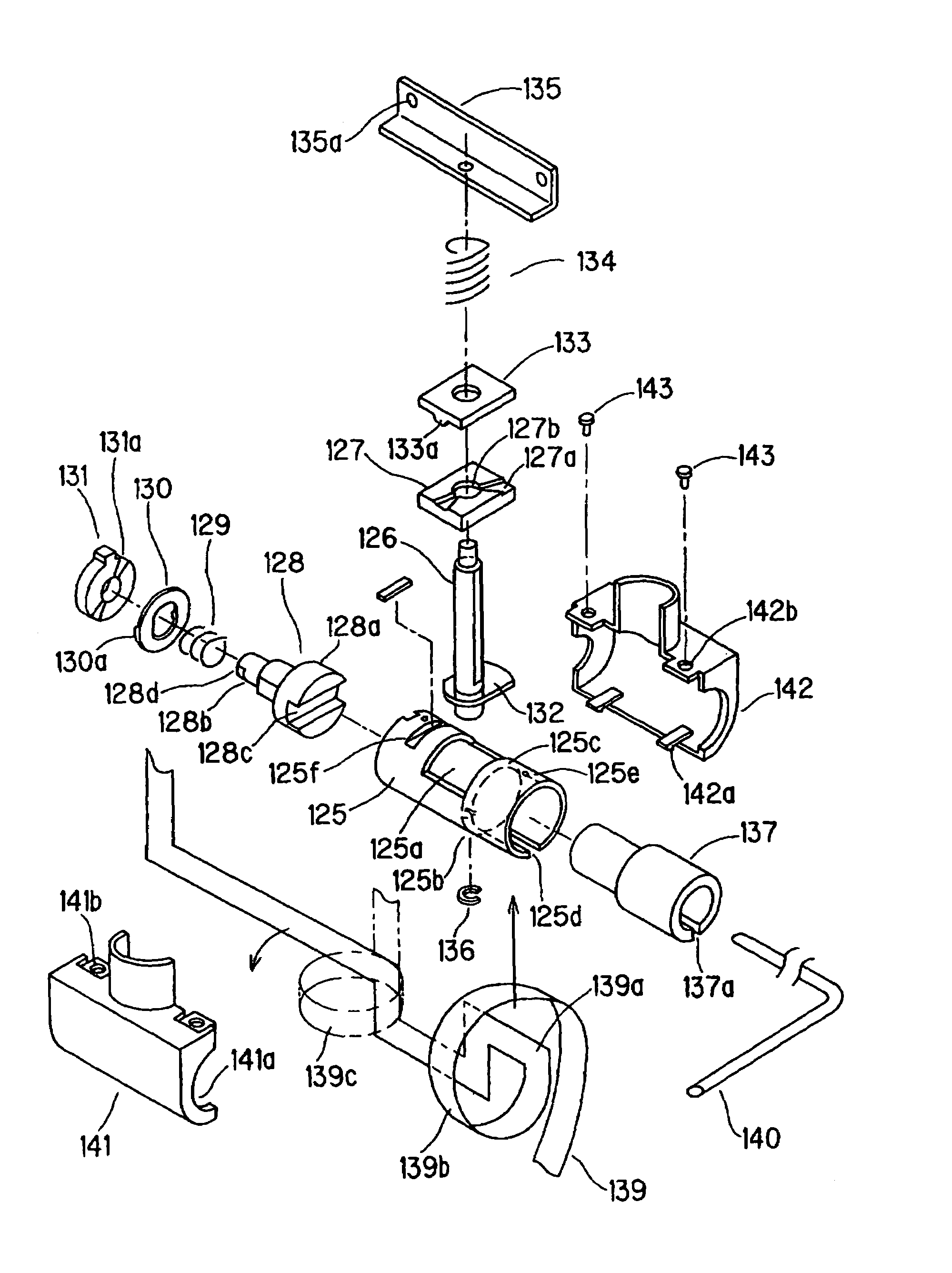
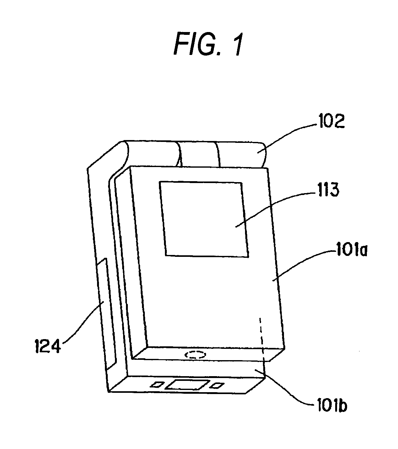
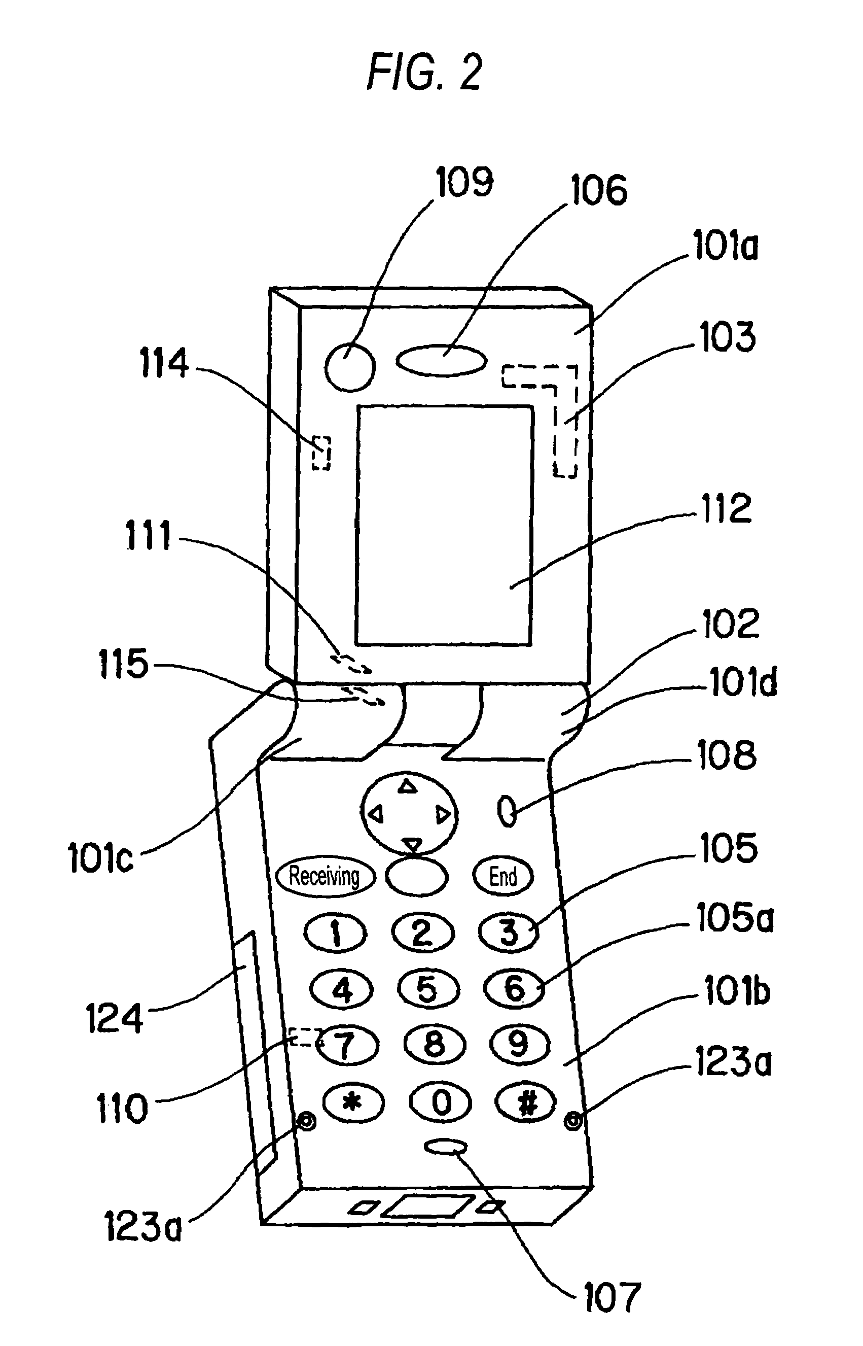
[0038]FIG. 1 is a perspective view for indicating a closed condition of a communication terminal according to an embodiment of the present invention. FIG. 2 is a perspective view for representing a first opened condition of the communication terminal according to the embodiment of the present invention. FIG. 3 is a perspective view for showing a second opened condition of the communication terminal according the embodiment of the present invention. FIG. 4 is a cross-sectional view of th...


PUM


Abstract

A purpose of the present invention is to provide a compact hinge apparatus in which a clearance between a rotating shaft and cover members is small and a rotation radius of the rotating shaft is small, and to provide an opening / closing type communication terminal equipped with the hinge apparatus. The hinge apparatus is comprised of: a hollow-shaped first rotating shaft (125) which can be pivotably moved; a second rotating shaft (126) which is intersected with this first rotating shaft (125) in a pivotable manner; a guide shaft (128) which is provided inside the first rotating shaft (125) and guides a cam (132) mounted on the second rotating shaft (126) at a predetermined position; a first casing member which is mounted on the first rotating shaft (125) in an integral manner; a second casing member which is mounted on the first rotating shaft in an integral manner; and both a front cover (141) and a rear cover (142), which cover both the first rotating shaft (125) and the second rotating shaft (126). In the hinge apparatus, the front cover (141) and the second cover (142) are fixed on the first rotating shaft (125) by a fastening screw (143).

Description

TECHNICAL FIELD[0001]The present invention is related to a compact hinge apparatus in which a clearance between a rotating shaft and a cover member is narrow and a rotation radius of the rotating shaft is small, and also, is related to an opening / closing type communication terminal equipped with this hinge apparatus.BACKGROUND ART[0002]As conventional opening / closing type communication terminals, for instance, an opening / closing type portable terminal apparatus is disclosed in JP-A-2001-251406, in which one casing is rotated along a direction perpendicular to an opening / closing direction. The opening / closing type portable terminal apparatus of this publication is arranged by employing an input unit for inputting information, a display unit for monitoring an operation condition and for displaying reception data, a control unit for controlling the input unit and the display unit, and a casing. It should be noted that the input unit owns a first input unit such as numeral keys, and a s...

Claims


Application Information

Patent Timeline
Patent Type & Authority Patents(United States)
IPC IPC(8): H04M1/00F16C11/10E05D3/04E05D3/10E05D11/10F16C11/04G06F1/16H04M1/02H04M1/21
CPCG06F1/162G06F1/1647G06F1/1677G06F1/1681G06F1/1683G06F1/1698H04M1/0212H04M1/0241E05D3/04Y10T16/540255E05D11/1078E05Y2900/606H04M2250/12H04M2250/16H04M2250/52Y10T16/52E05D3/10
Inventor SATOH, NORIYOSHITAKAMORI, KAZUAKI
Owner PANASONIC CORP
Why Eureka
Try Eureka