Tension shackle x-brace

a technology of x-brace and shackle, which is applied in the direction of suspensions, resilient suspensions, vehicle components, etc., can solve the problems of poor handling, poor performance, and inherent weakness of torsional stiffness and rigidity of vehicle ladder-type frame constructions

Inactive Publication Date: 2007-09-25
TOYOTA MOTOR CO LTD
View PDF15 Cites 14 Cited by
  • Summary
  • Abstract
  • Description
  • Claims
  • Application Information

AI Technical Summary

Benefits of technology

[0003]The present invention seeks to provide a device for reinforcing the ladder type vehicle frame, particularly for a pickup truck, SUV or similar vehicle having a ladder-type frame, to enhance the torsional stiffness of the frame adjacent the rear end of the vehicle. The ladder-type frame includes two longitudinal parallel side rails or beams upon which the suspension and engine are mounted such that the beams operate as carriers for these loads and others. Suspension attachments are also disposed on the side rails of the frame for mounting members of the vehicle suspension, such as leaf springs, coil springs, shock absorbers, lateral links, longitudinal links, and the like.
[0006]As described, the device for reinforcement of a ladder-type frame of a vehicle is provided which adds torsional rigidity to the frame and rear suspension for aggressive driving or off-roading.

Problems solved by technology

It has been known that vehicle ladder-type frame constructions have an inherent weakness with regard to torsional stiffness and rigidity.
Although the ladder-type frame is good for carrying direct loads, it handles poorly due to its lack of torsional stiffness and therefore can perform poorly during aggressive on-road driving or when subject to severe forces from off-road driving.
It is also known that large lateral deflections may occur at the leaf spring hangers or other suspension attachment points when vehicles having the ladder-type frame are subjected to such type of aggressive driving.
These types of deflections can result in poor suspension feedback to the driver, and in severe cases may lead to substantial vehicle damage as well as possible, vehicle rollover due to instability.

Method used


Image

  • Tension shackle x-brace
  • Tension shackle x-brace
  • Tension shackle x-brace

Examples


Embodiment Construction

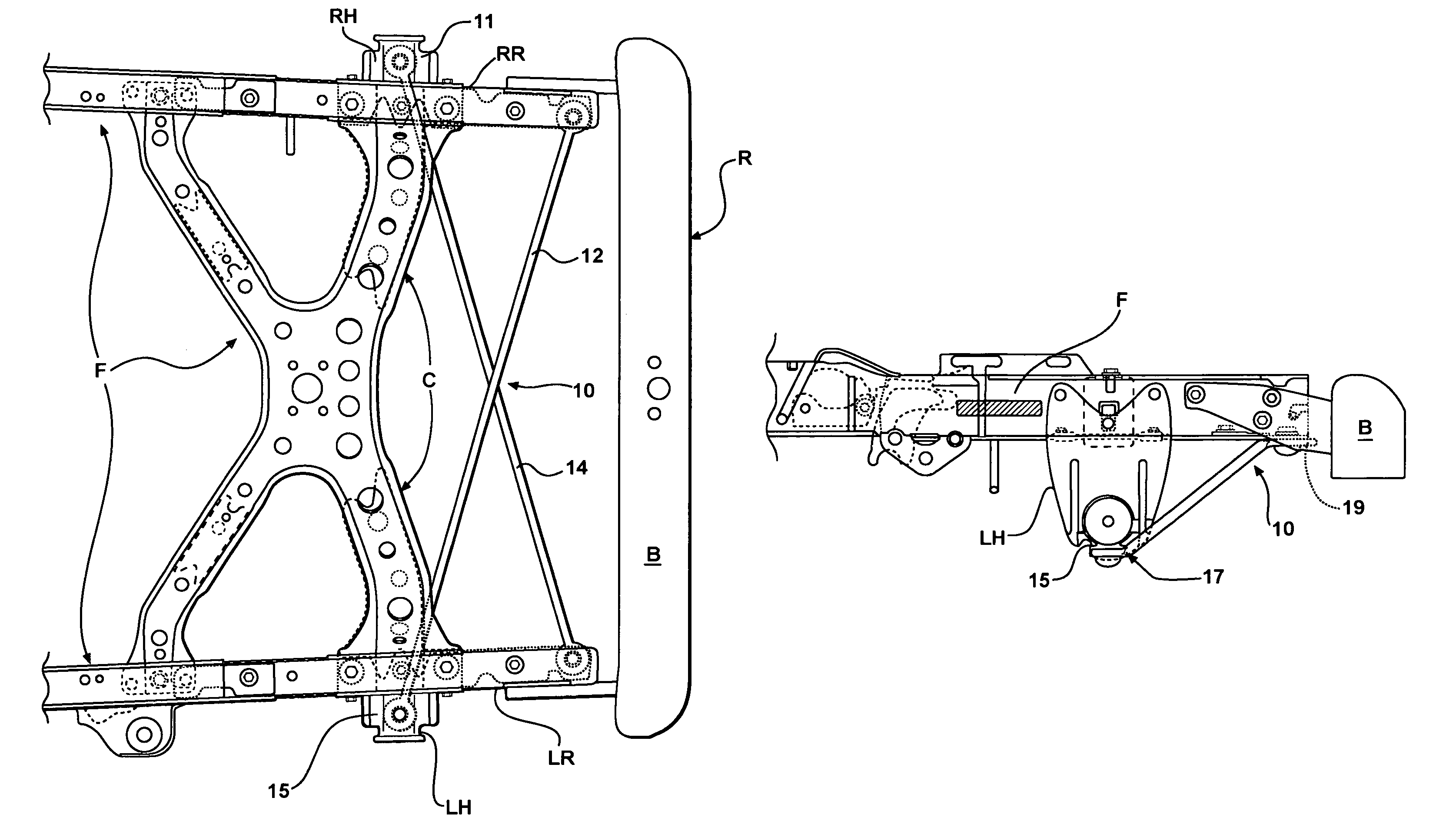
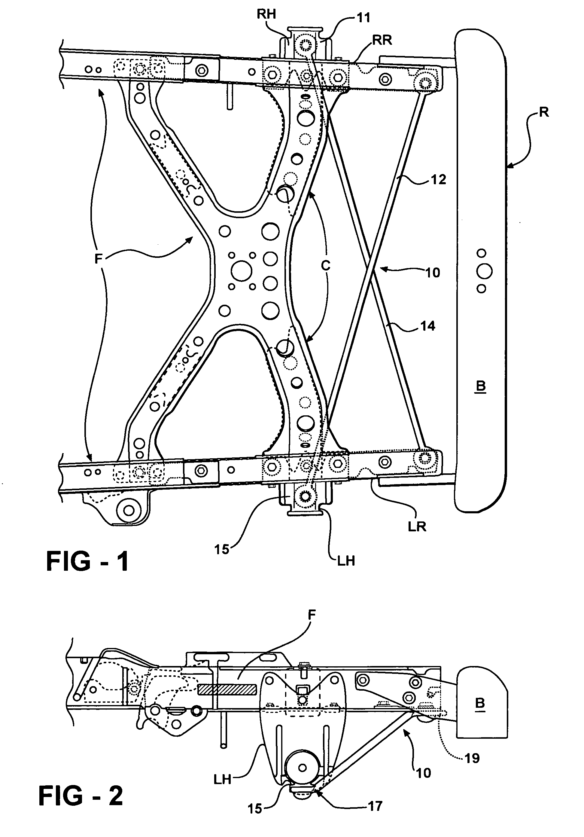
[0011]The present invention provides a device that is attachable to a ladder-type vehicle frame to enhance the structural rigidity of the frame and to minimize the magnitude of lateral deflections that occur at the suspension attachments when the vehicle is used in off-roading or aggressive driving. The device is an advantageous alternative to providing additional frame cross-members which increases the vehicle mass and the cost of manufacturing. The device is adapted to be selectively attachable to the vehicle and is formed from a lightweight high strength material operative to enhance torsional rigidity without substantially increasing the mass and cost of the vehicle.

[0012]Referring now to FIG. 1, the device 10 for reinforcing the ladder-type frame F of a vehicle is provided being disposed at the rear end R of the ladder-type frame F of a vehicle.

[0013]Illustratively, a ladder-type frame F includes left and right-side rails (LR, RR) provided as two longitudinal parallel beams upo...


PUM


Abstract

The present invention provides a device for reinforcing the rear end of a vehicle having a ladder-type frame. The device includes a first bar that is adapted to be secured between the left side rail and right suspension attachment of the vehicle frame and a second bar adapted to be secured between the right side rail and left suspension attachment such that the first and second bars are mounted to the frame in a crosswise fashion with respect to each other between the side rails. The device is mounted adjacent the rear of the vehicle frame whereby torsional stiffness and rigidity can be added to the rear of the frame and lateral deflection of the suspension attachments that occurs during aggressive driving is sharply minimized.

Description

FIELD OF THE INVENTION[0001]The present invention relates to automotive vehicle frames and more particularly to a reinforcement device for use with ladder-type frames such as those used on pick up trucks, SUVs, and the like to enhance torsional stiffness and reduce compliance of the suspension attachment points.BACKGROUND OF THE INVENTION[0002]It has been known that vehicle ladder-type frame constructions have an inherent weakness with regard to torsional stiffness and rigidity. Although the ladder-type frame is good for carrying direct loads, it handles poorly due to its lack of torsional stiffness and therefore can perform poorly during aggressive on-road driving or when subject to severe forces from off-road driving. It is also known that large lateral deflections may occur at the leaf spring hangers or other suspension attachment points when vehicles having the ladder-type frame are subjected to such type of aggressive driving. These types of deflections can result in poor suspe...

Claims


Application Information

Patent Timeline
Patent Type & Authority Patents(United States)
IPC IPC(8): B62D21/00B62D21/02B62D21/09B62D21/11
CPCB62D21/02B62D21/09
Inventor KIEL, KEVIN HENRYPROVOST, IV, STEPHEN BISHOP
Owner TOYOTA MOTOR CO LTD
Why Eureka
Try Eureka