Continuously variable transmission

a transmission and variable technology, applied in the field of transmission, can solve problems such as limited torque capacity

Active Publication Date: 2007-09-25
TROESTER THOMAS F
View PDF4 Cites 13 Cited by
  • Summary
  • Abstract
  • Description
  • Claims
  • Application Information

AI Technical Summary

Benefits of technology

[0009]Another object of this invention is to provide cones as previously described with an under cut at the theoretical geared neutral to limit the theoretical infinite torque at either side of neutral. Other objects of this invention will become apparent upon a reading of the following description.

Problems solved by technology

Most utilize friction in the drive mechanism and are therefore somewhat limited in torque capacity.

Method used


Image

  • Continuously variable transmission
  • Continuously variable transmission
  • Continuously variable transmission

Examples


Embodiment Construction

[0029]The preferred embodiments illustrated are not intended to be exhaustive or to limit the invention to the precise forms disclosed. They are chosen and described in order to explain the principles of the invention and its application and practical use to thereby enable others skilled in the art to use the invention.

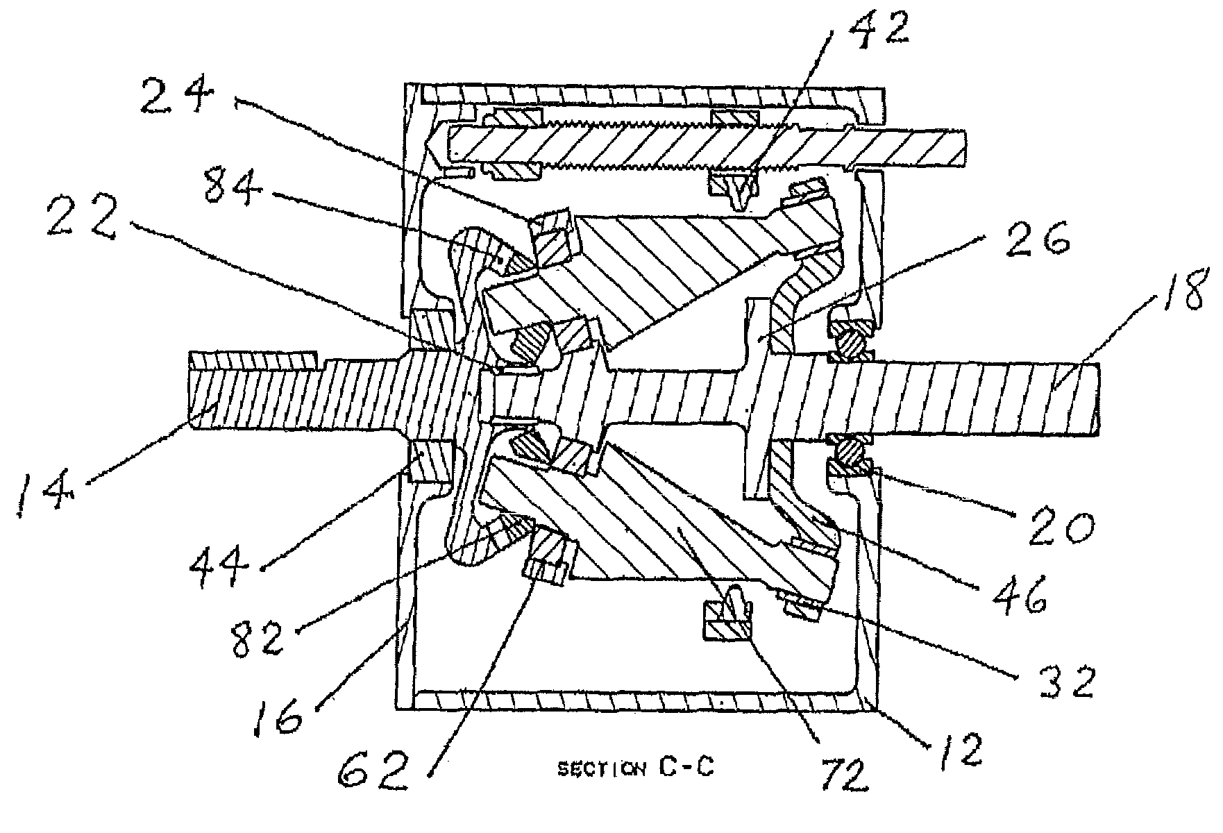
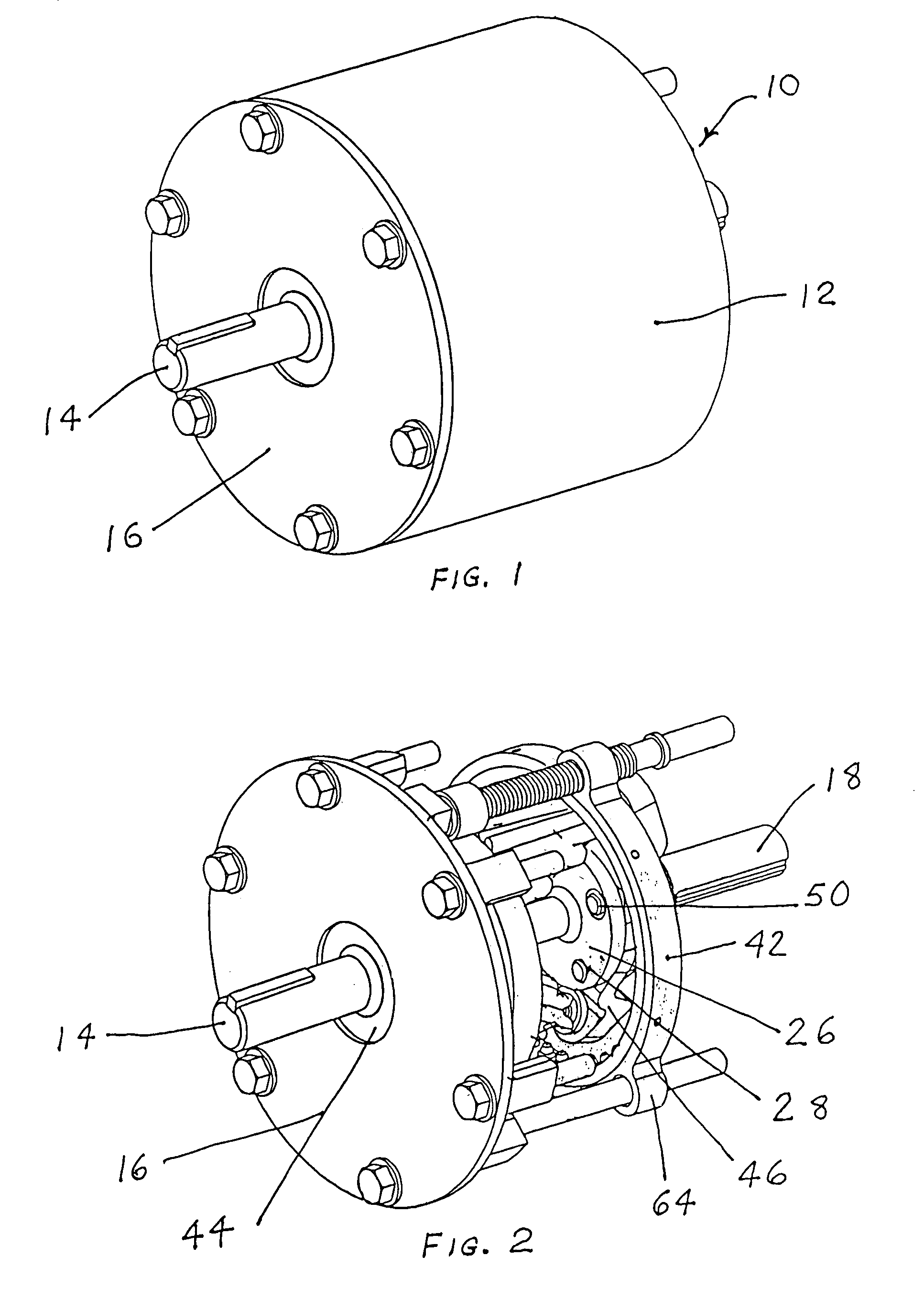
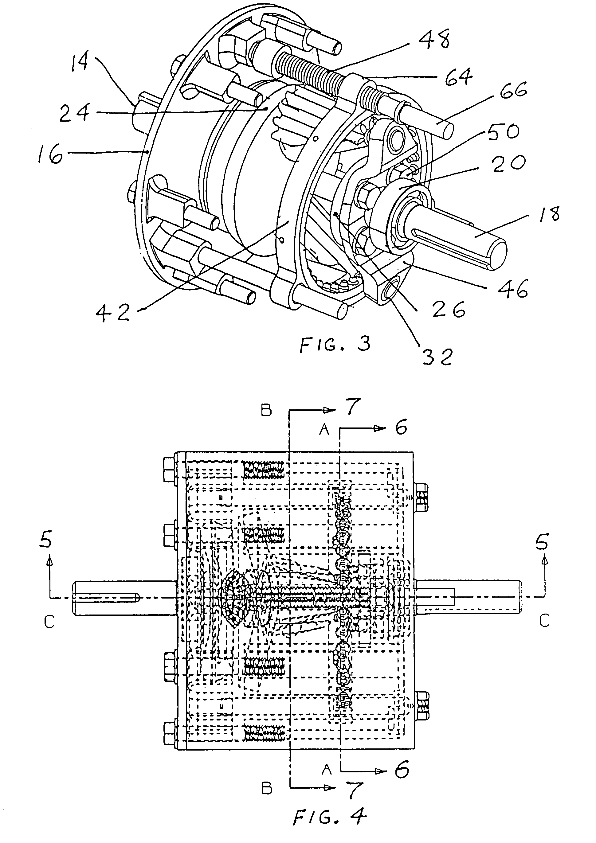
[0030]An embodiment of the continuously variable transmission 10 is shown in FIG. 1. Transmission 10 includes housing 12 and output shaft 14 journaled by bearings 44 which are preferable of the sealed ball type and mounted in the housing cover 16. An input shaft 18 is journaled at one side by bearings 20 which are preferable of the sealed ball type and are mounted in housing 12. Input shaft 18 is journaled at one end in the body of output shaft 14 by bearings 22 which are preferable of the needle roller type. A first pair of arms 24 extends radially outward from input shaft 18 and are angled transversely to the axis of the input shaft. Arms 24 are oppositely spaced up...


PUM


Abstract

A constant mesh gear driven continuously variable transmission including a minimum of two cones in mesh with either an axial sliding ring gear or an axial sliding circular gear. The cones and ring gear or circular gear are enclosed in a housing. An input shaft is journaled in the housing. The cones rotate about their own axes and revolve about the shaft in some embodiments. The ring gear or axial sliding circular gear is slidable axially relative to the cone gear, and the output gear ratio is varied by the axial position on the ring gear or sliding circular gear.

Description

CROSS-REFERENCE TO RELATED APPLICATION[0001]This application claims the benefit of and is a continuation in part of provisional application Ser. No. 60 / 561,577, filed Apr. 14, 2004.BACKGROUND OF THE INVENTION[0002]This invention relates to a transmission having specific application to the automotive industry, but is not intended to be so limited. Other applications are the aerospace industry, or many other applications where speed change devices are desired.[0003]There are many continuously variable transmissions (CVT). Most utilize friction in the drive mechanism and are therefore somewhat limited in torque capacity. The split pair of variable diameter pulleys and belt CVTs (Van Doorne) common in today's automobiles utilizes friction. There are other CVTs that utilize cones, but they use friction as a drive mechanism. This invention as well as U.S. Pat. No. 4,680,985, incorporated herein by reference, utilizes constant mesh gear cones. This invention is novel in the interface and c...

Claims


Application Information

Patent Timeline
Patent Type & Authority Patents(United States)
IPC IPC(8): F16H3/50
CPCF16H3/76
Inventor TROESTER, THOMAS F.
Owner TROESTER THOMAS F
Why Eureka
Try Eureka