Expandable liner hanger system and method

a liner hanger and expandable technology, applied in the direction of drilling casings, drilling pipes, borehole/well accessories, etc., can solve the problems of affecting the setting operation, difficult retrieval, and other liner hangers and running tools cannot perform conventional cementing operations, etc., to achieve the effect of high reliability and construction more economically

Active Publication Date: 2007-10-09
TIW
View PDF7 Cites 52 Cited by
  • Summary
  • Abstract
  • Description
  • Claims
  • Application Information

AI Technical Summary

Benefits of technology

[0010]The present invention preferably uses a tubular expander to expand the hanger body, and which remains positioned inside the expanded hanger body for support at its final expanded diameter, thus sandwiching the expanded plastically deformed hanger body between the casing and the tubular expander. This method provides improved sealing and gripping capability and requires shorter lengths of expandable tubular liner hanger, typically in the range of from one to two feet.
[0012]The tubular liner hanger body may be axially interconnected with a running tool mandrel by a collet or other latch mechanism, which is prevented from moving radially inward by a stop when the liner is run in the well. The latch mechanism moves axially relative to the stop after the tubular expander is positioned within the liner hanger body and the work string is subsequently lowered. A catch mechanism interconnects the latch mechanism and the running tool mandrel, thereby allowing the latch mechanism to move radially inward and release the running tool from the set liner hanger without rotating the running string.
[0015]Another feature is that the running tool actuator may be reliably released from the set liner hanger assembly after expansion of the liner hanger body without rotating the work string. Interference between the tubular expander and the liner hanger body secures the tubular expander within the liner hanger body. The running tool may then be removed from the well.
[0016]An advantage is that the liner hanger may be constructed more economically than other prior art liner hangers. The assembly consists of few components. A related advantage is that many of the components of the assembly, such as slips and packer seals, may be commercially available in accordance with various downhole conditions.
[0017]Another advantage is that the system for forming a liner hanger may utilize conventional components each with a high reliability. Existing personnel with a minimum of training may reliably use the liner hanger system according to this invention since the invention relies upon well known surface operations to reliably form the liner hanger.

Problems solved by technology

Liner hangers with multiple parts pose a significant liability when one or more of the parts becomes loose in the well, thereby disrupting the setting operation and making retrieval difficult.
Other liner hangers and running tools cannot perform conventional cementing operations through the running tool before setting the liner hanger in the well.
Other liner hangers have problems supporting heavy liners with the weight of one million pounds or more.
Some liner hangers successfully support the liner weight, but do no reliably seal with the casing string.
After the liner hanger is set in the well, high fluid pressure in the annulus between the liner and the casing may blow by the liner hanger, thereby defeating its primary purpose.
Other liner hangers are not able to obtain burst and / or collapse characteristics equal to that of the casing.
The subsequent relaxation of the energy necessary to maintain the liner hanger at the fully expanded diameter may thus lead to a failure of sealing and / or suspension supporting capability.
Another significant problem with some liner hangers is that the running tool cannot be reliably disengaged from the set liner hanger.
This problem with liner hanger technology concerns the desirability to rotate the liner with the work string in the well, then disengage from the work string when the liner hanger has been set to retrieve the running tool from the well.

Method used


Image

  • Expandable liner hanger system and method
  • Expandable liner hanger system and method
  • Expandable liner hanger system and method

Examples


Embodiment Construction

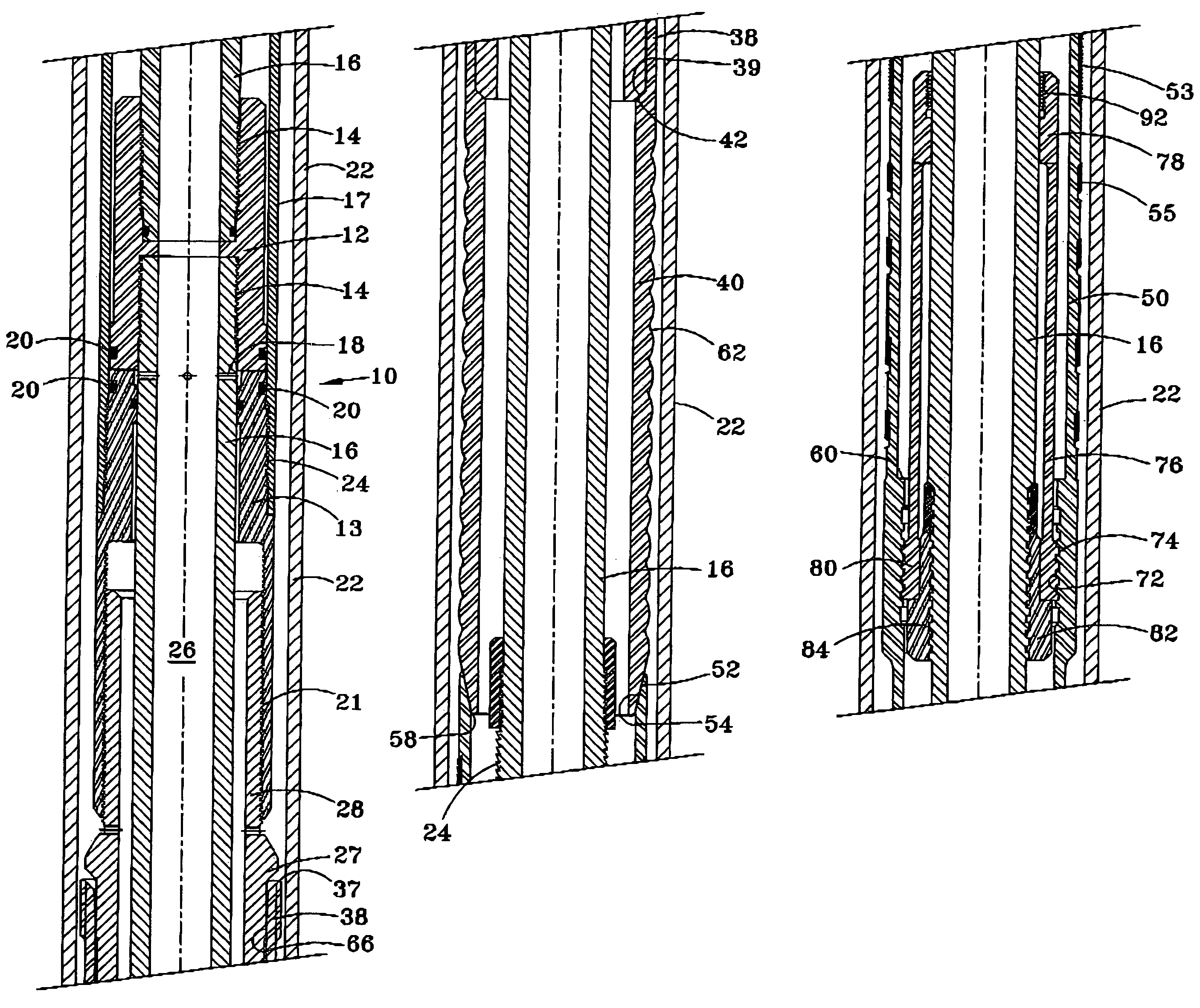
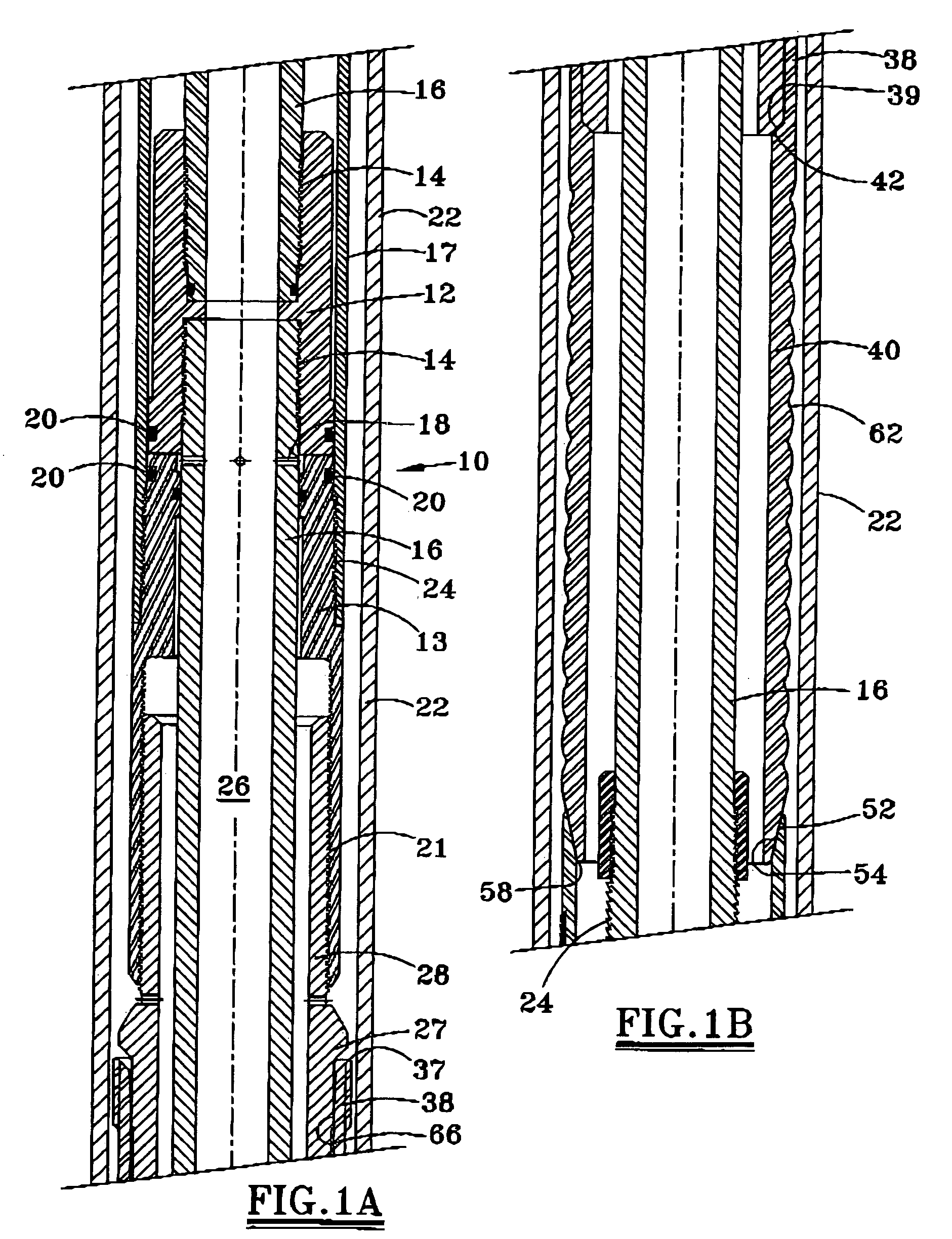
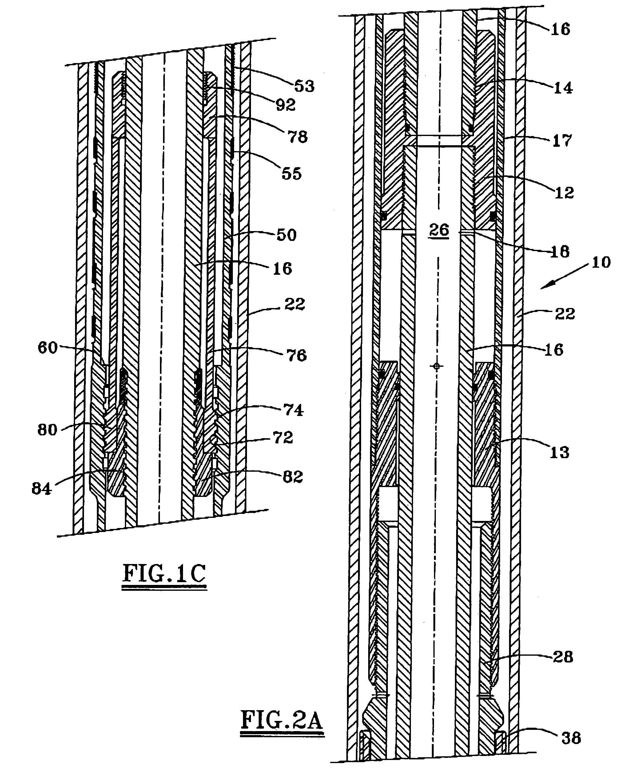
[0024]A liner may be conveyed into the well to the desired setting or suspension depth by a drill pipe or work string connected to a multi-stage, double action hydraulic setting and releasing tool (running tool) that furnishes the necessary forces to expand the liner hanger assembly into engagement with the casing. The running tool may be constructed of sufficiently high strength steel to support the weight of the liner as it is run into the well and to provide the necessary force to expand the liner hanger assembly. Additionally, the running tool preferably has a sufficiently large internal bore in its central mandrel to enable passage and displacement of cement for cementing the liner within the well bore.

[0025]Referring to FIG. 1A, the upper end of the running tool actuator assembly 10 may include a top connector 12 structurally connected by threads 14 to the running tool inner mandrel 16, which in turn is structurally at the lower end of a work string. A throughport 18 in the ma...


PUM


Abstract

A liner hanger assembly seals with casing 22 and supports a liner 90 within a well. The tubular liner hanger body 50 and a tubular expander 40 may be positioned downhole at a desired depth on a running tool. An actuator assembly 12, 24 may forcibly move the tubular expander 40 into the liner hanger body 50, expanding the liner hanger body to seal and secure the hanger body to the casing string 22. The running tool may be released from the set liner hanger by an axially movable collet mechanism, such as ratchet ring 92 and a catch mechanism, such as threads 94. The running string thus need not be rotated to release from the set liner hanger.

Description

RELATED APPLICATION[0001]This application is a continuation-in-part of U.S. Ser. No. 10 / 855,044 filed May 27, 2004 now U.S. Pat. No. 7,225,880.FIELD OF THE INVENTION[0002]The present invention relates to downhole tools and techniques for hanging a liner in a well. More particularly, the invention relates to forming an expandable liner hanger assembly for grippingly engaging a casing string to support the liner in the well. The running tool may be released from the set liner hanger without rotation of the work string.BACKGROUND OF THE INVENTION[0003]Various types of liner hangers have been proposed for hanging a liner from a casing string in a well. Most liner hangers are set with slips activated by the liner hanger running tool. Liner hangers with multiple parts pose a significant liability when one or more of the parts becomes loose in the well, thereby disrupting the setting operation and making retrieval difficult. Other liner hangers and running tools cannot perform conventional...

Claims


Application Information

Patent Timeline
Patent Type & Authority Patents(United States)
IPC IPC(8): E21B23/00E21B43/10
CPCE21B43/106E21B43/103
Inventor BRADDICK, BRITT O.
Owner TIW
Why Eureka
Try Eureka