Digital-to-analog converter using a frequency hopping clock generator

Active Publication Date: 2007-10-09
INFINEON TECH AG
View PDF28 Cites 8 Cited by
  • Summary
  • Abstract
  • Description
  • Claims
  • Application Information

AI Technical Summary

Benefits of technology

[0014]The present invention provides a method and a device which make it possible to suppress or attenuate the signal images at the output of a digital / analog converter.
[0016]The frequency hopping method is a known technique, which is commonly used in telecommunications systems. It is characterized by a carrier frequency of the transmitter changing (“hopping”) periodically in the time domain. The frequency changes are given by a frequency sequence f1, f2, f3, . . . . The receiver knows the frequency sequence and is constantly tuned to the current carrier frequency of the transmitter in accordance with the sequence. The frequency hopping method allows low-perturbation signal transmission, since interference in one of the frequency channels impairs the transmission quality only briefly because of the rapid frequency change. The frequency hopping method furthermore guarantees a high degree of data security, since external receivers do not know the frequency sequence and can therefore be tuned to the transmitter only rarely or briefly.
[0018]One advantage of the method according to the invention is that the smoothing filter may either be entirely obviated or may have a lower order.

Problems solved by technology

The frequency hopping method allows low-perturbation signal transmission, since interference in one of the frequency channels impairs the transmission quality only briefly because of the rapid frequency change.

Method used


Image

  • Digital-to-analog converter using a frequency hopping clock generator
  • Digital-to-analog converter using a frequency hopping clock generator
  • Digital-to-analog converter using a frequency hopping clock generator

Examples


Embodiment Construction

[0036]One or more implementations of the present invention will now be described with reference to the attached drawings, wherein like reference numerals are used to refer to like elements throughout, and wherein the illustrated structures are not necessarily drawn to scale.

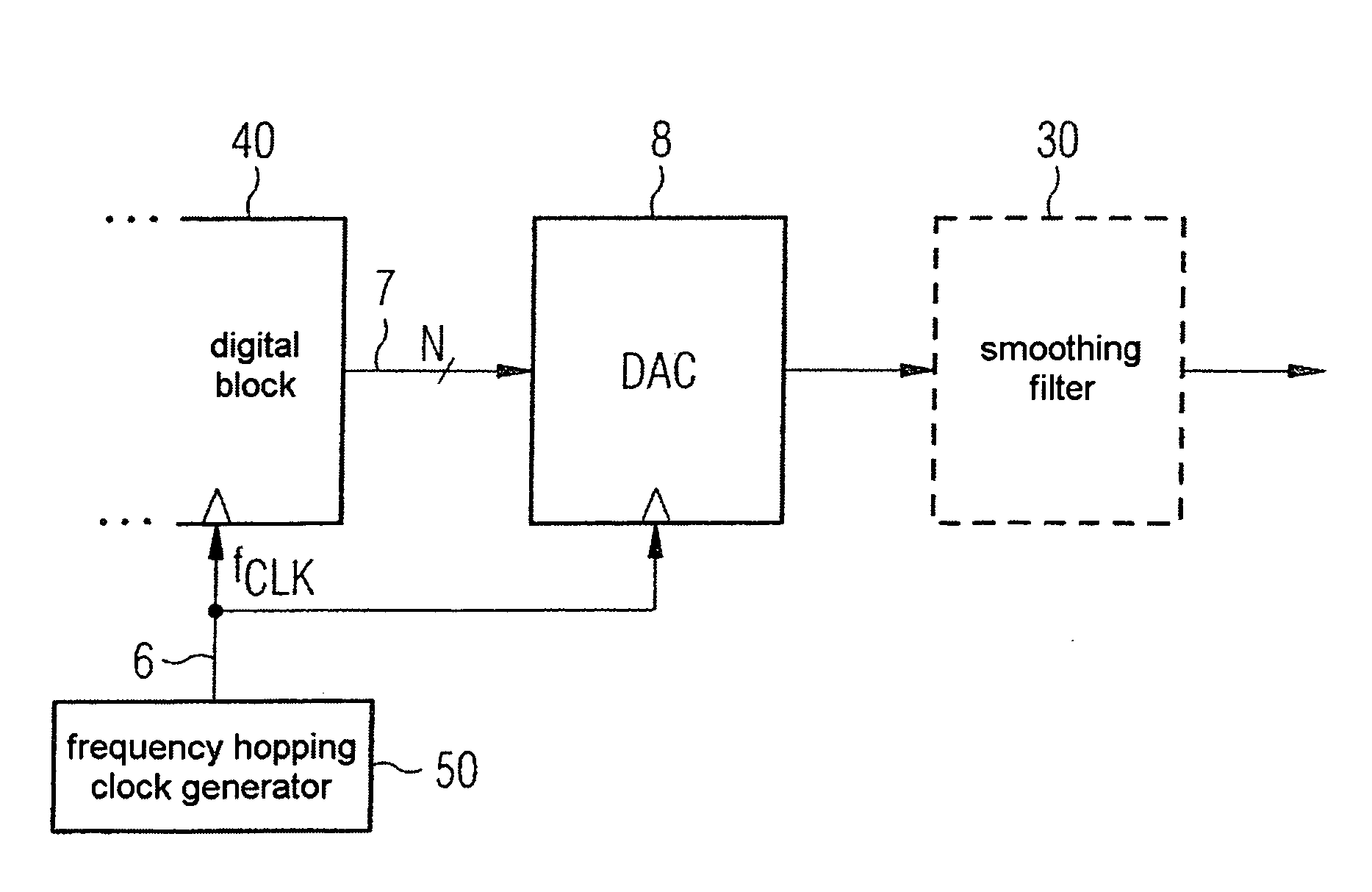
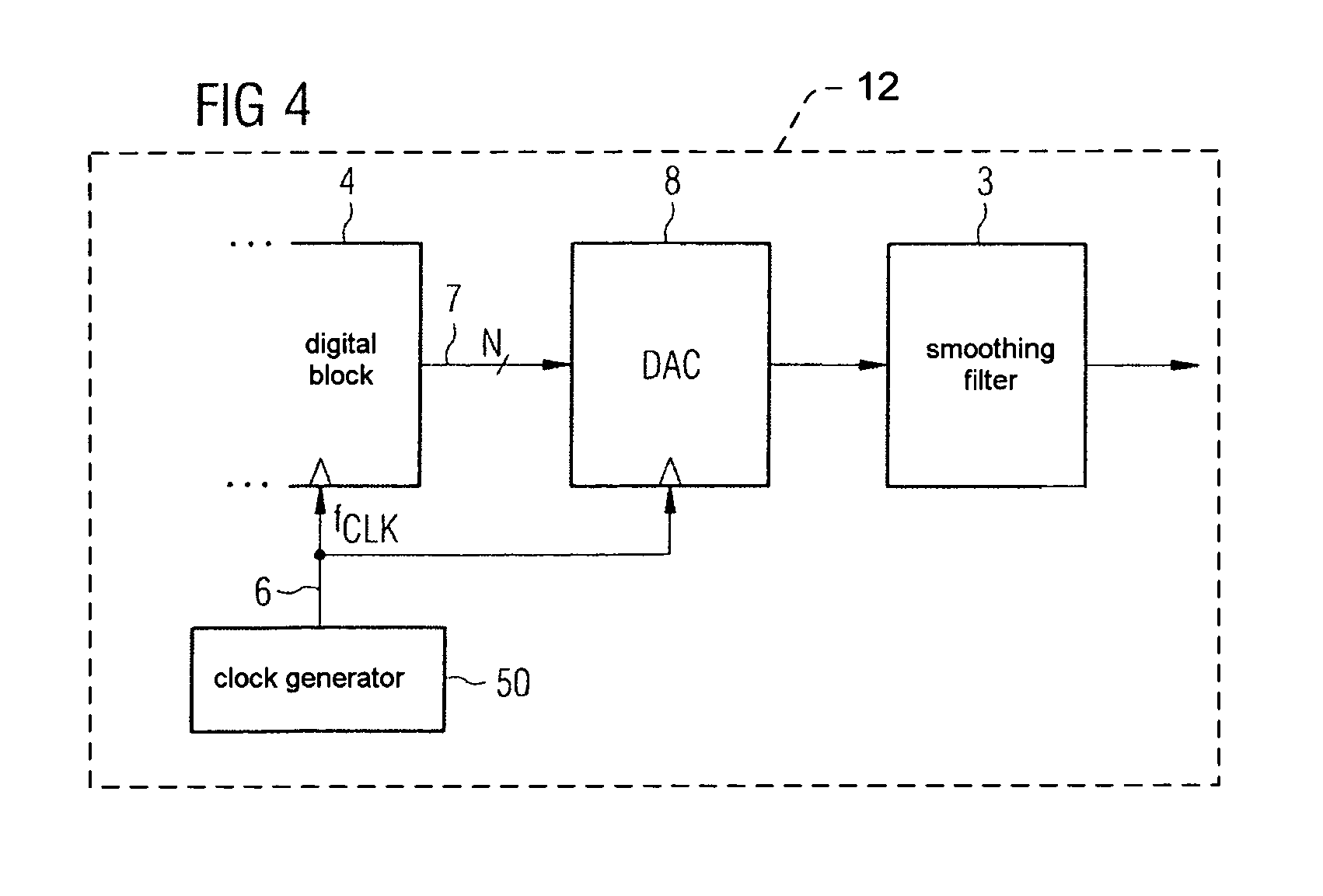
[0037]According to FIG. 4, a digital block 4 is driven by a clock generator 5 which emits a clock signal 6 with a fixed clock frequency fCLK, wherein the digital block 4 and clock generator 5 may be included in a receiver 12. The digital block 4 delivers digital data words (word width N) via a data connection 7 to a digital / analog converter 8. The data rate is fCLK, i.e. it corresponds to the clock frequency of the clock signal.

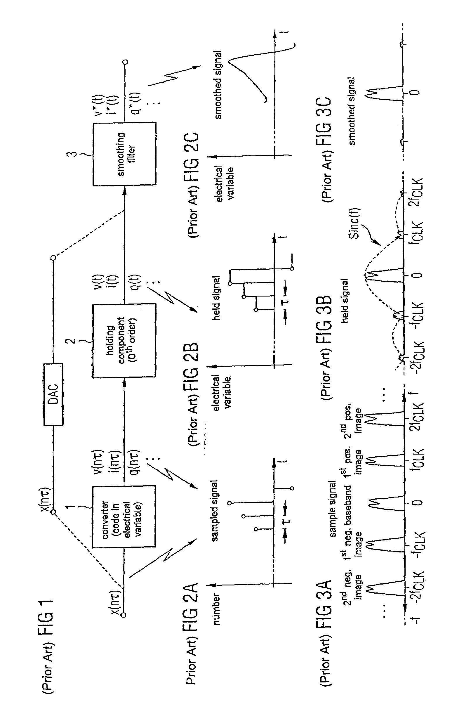
[0038]The clock signal 6 furthermore drives the clock input of the digital / analog converter 8. The mode of operation of the digital / analog converter 8 and of the downstream smoothing filter 3 have already been described in relation to FIGS. 1-3C.

[0039]FIG. 5 shows an exemplary embodiment o...


PUM


Abstract

Method and device for reducing the signal images at the output of a digital / analog converter. In a method for reducing the signal images at the output of a digital / analog converter, a frequency hopping clock generator provides a digital data signal whose data rate is varied according to a frequency hopping method. The digital data signal is converted into an analog signal by a digital / analog converter, the conversion clock being varied according to the frequency hopping method.

Description

REFERENCE TO RELATED APPLICATIONS[0001]This application claims the benefit of the priority date of German application DE 10 2004 024 645.9, filed on May 18, 2004, the contents of which are herein incorporated by reference in their entirety.FIELD OF THE INVENTION[0002]The invention relates to a method and a device for reducing the signal images at the output of a digital / analog converter.BACKGROUND OF THE INVENTION[0003]A synchronous digital / analog converter (DAC) may be regarded according to FIG. 1 as a circuit which consists of a converter 1 and a holding component 2. This DAC circuit simultaneously implements the following two operations:[0004]converting a number x(nτ) into an electrical variable, for example voltage v(nτ), current i(nτ) or charge q(nτ). The number x(nτ) is usually represented in a binary code. The quantity τ denotes the sampling period, and n denotes the discrete time.[0005]keeping the electrical variable constant over a time interval which corresponds to the sam...

Claims


Application Information

Patent Timeline
Patent Type & Authority Patents(United States)
IPC IPC(8): H03M1/66H03M3/00H03M1/06H03M7/00
CPCH03M1/0656H03M3/336H03M3/502H03M1/66H03M3/3283
Inventor DIAS, VICTOR
Owner INFINEON TECH AG
Why Eureka
Try Eureka