Supercharge Your Innovation With Domain-Expert AI Agents!

Eye safety logic with compensation for transient conditions

a technology of transient conditions and safety logic, applied in the field of telecommunications systems, can solve problems such as unnecessarily turning off the laser

Active Publication Date: 2007-10-09
II VI DELAWARE INC
View PDF8 Cites 8 Cited by
  • Summary
  • Abstract
  • Description
  • Claims
  • Application Information

AI Technical Summary

Benefits of technology

[0010]The foregoing problems with the prior state of the art are overcome by the principles of the present invention. The principles of the present invention relates to an eye safety detection circuit for use in a laser transmitter. The eye safety detection circuit shuts the laser down if the laser is emitting excessive optical energy to the point of being unsafe to a user. However, the eye safety detection circuit avoids shut down when there is no real threat to a surrounding user due to a transient condition such as, for example, during start up of the laser transmitter.
[0011]The eye safety detection circuit includes a laser current detection circuit that is configured to detect when there is a potential that the laser is emitting light at levels that exceed a predetermined threshold. If the laser were to immediately turn off under this condition, the laser may be turned off unnecessarily, for there may be transient conditions that affect any given instantaneous level of laser emissions. Instead, the eye safety detection circuit includes a timer circuit that causes the laser to cease operation only after one or more conditions have been met for a predetermined period of time. Therefore, laser shut down is avoided in transient conditions in which there is no significant safety concern, while performing laser shut down in the case of a more persistent problem.

Problems solved by technology

The eye safety detection circuit shuts the laser down if the laser is emitting excessive optical energy to the point of being unsafe to a user.
If the laser were to immediately turn off under this condition, the laser may be turned off unnecessarily, for there may be transient conditions that affect any given instantaneous level of laser emissions.

Method used


Image

  • Eye safety logic with compensation for transient conditions
  • Eye safety logic with compensation for transient conditions
  • Eye safety logic with compensation for transient conditions

Examples


Embodiment Construction

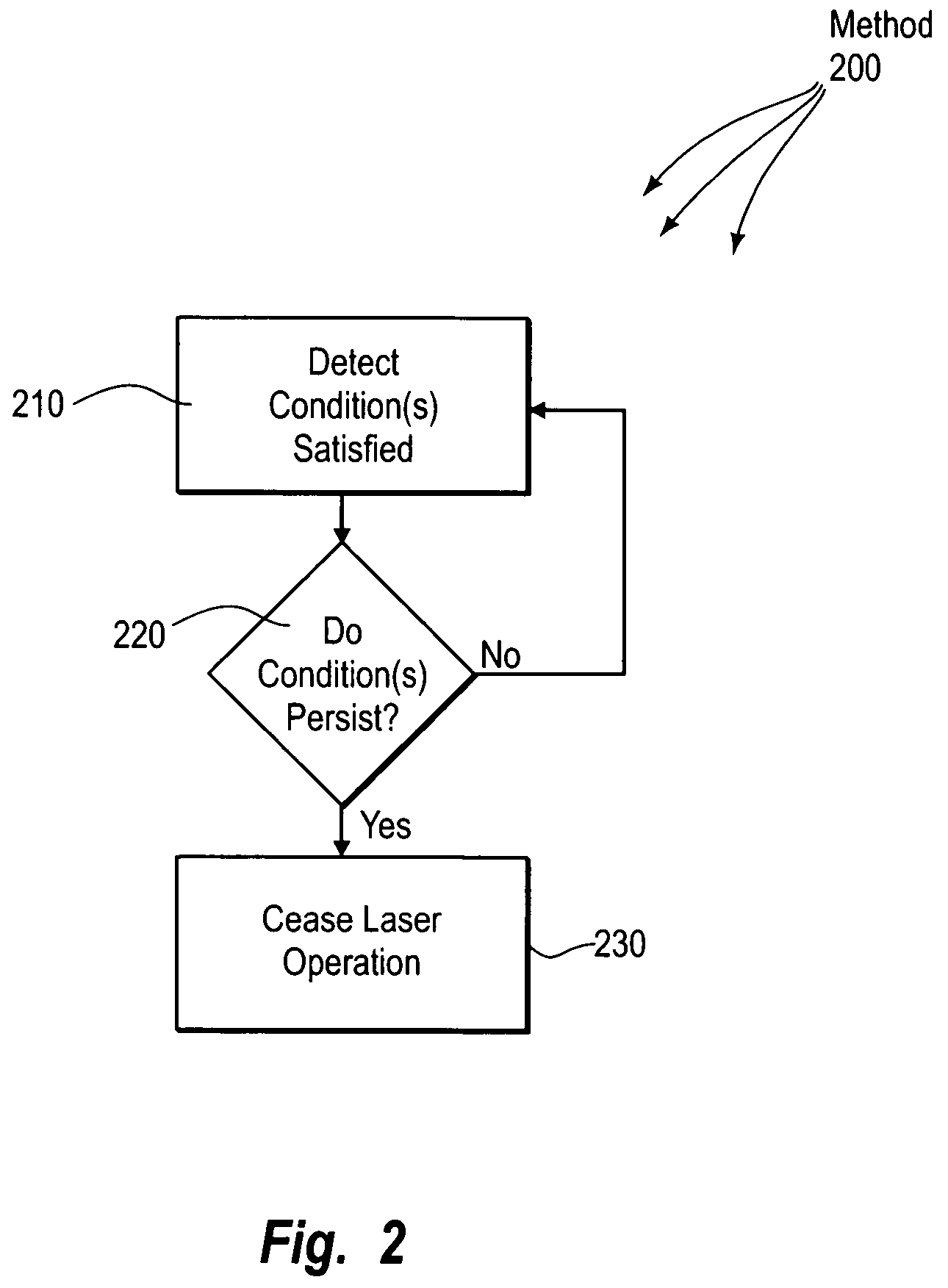
[0018]The principles of the present invention relate to an eye safety detection circuit for use in a laser transmitter. The eye safety detection circuit shuts the laser down if the laser is emitting excessive optical energy to the point of being unsafe to a user. However, the eye safety detection circuit avoids shut down in transient conditions when there is no real threat to a surrounding user due to a transient condition such as, for example, the start up of the laser transmitter.

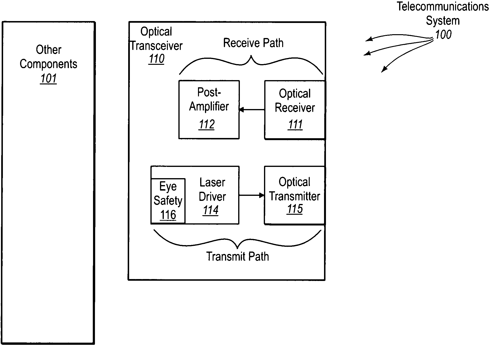
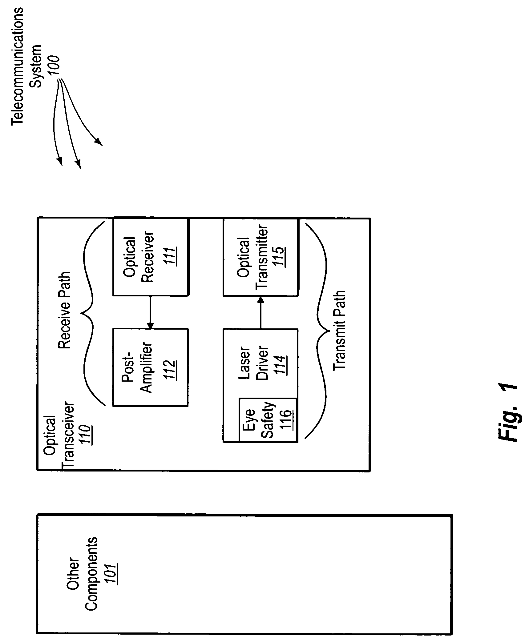
[0019]Turning to the drawings, FIG. 1 schematically illustrates a telecommunications system 100 that includes an optical transceiver 110 amongst potentially other components 101. The optical transceiver 110 operates to receive an incoming optical signal and report the signal to the other components 101. Specifically, an optical receiver 111 receives the incoming optical signal and converts the optical signal into a corresponding electrical signal. The electrical signal is then provided to a post-amplifier...


PUM


Abstract

An eye safety detection circuit for use in a laser transmitter. The eye safety detection circuit shuts the laser down if the laser is emitting excessive optical energy to the point of being unsafe to a user. The eye safety detection circuit includes a laser current detection circuit that is configured to detect when there is a potential that the laser is emitting light at levels that exceed a predetermined threshold. If the laser were to immediately turn off under this condition, the laser may be turned off prematurely. Instead, the eye safety detection circuit includes a timer circuit that causes the laser to cease operation only after one or more such conditions have been met for a predetermined period of time.

Description

CROSS-REFERENCE TO RELATED APPLICATIONS[0001]This application claims the benefit of United States Provisional Application No. 60 / 550,587 filed Mar. 5, 2004, which is incorporated herein by reference in its entirety.BACKGROUND OF THE INVENTION[0002]1. The Field of the Invention[0003]The present invention relates generally to telecommunications systems. More particularly, the present invention relates to an eye safety shutdown mechanism in a laser transmitter with compensation for transient conditions such as start-up conditions.[0004]2. Background and Relevant Art[0005]Fiber optic technology is increasingly employed as a method by which information can be reliably transmitted via a communications network. Networks employing fiber optic technology are known as optical communications networks, and are marked by high bandwidth and reliable, high-speed data transmission.[0006]Optical communications networks employ optical transceivers in transmitting information via the network from a tr...

Claims


Application Information

Patent Timeline
Patent Type & Authority Patents(United States)
IPC IPC(8): H01S3/00H01S3/10H01S5/068
CPCH01S5/06825
Inventor MORAN, TIMOTHY G.LIGHT, GRETA
Owner II VI DELAWARE INC
Features
  • R&D
  • Intellectual Property
  • Life Sciences
  • Materials
  • Tech Scout
  • Unparalleled Data Quality
  • Higher Quality Content
  • 60% Fewer Hallucinations
Learn More